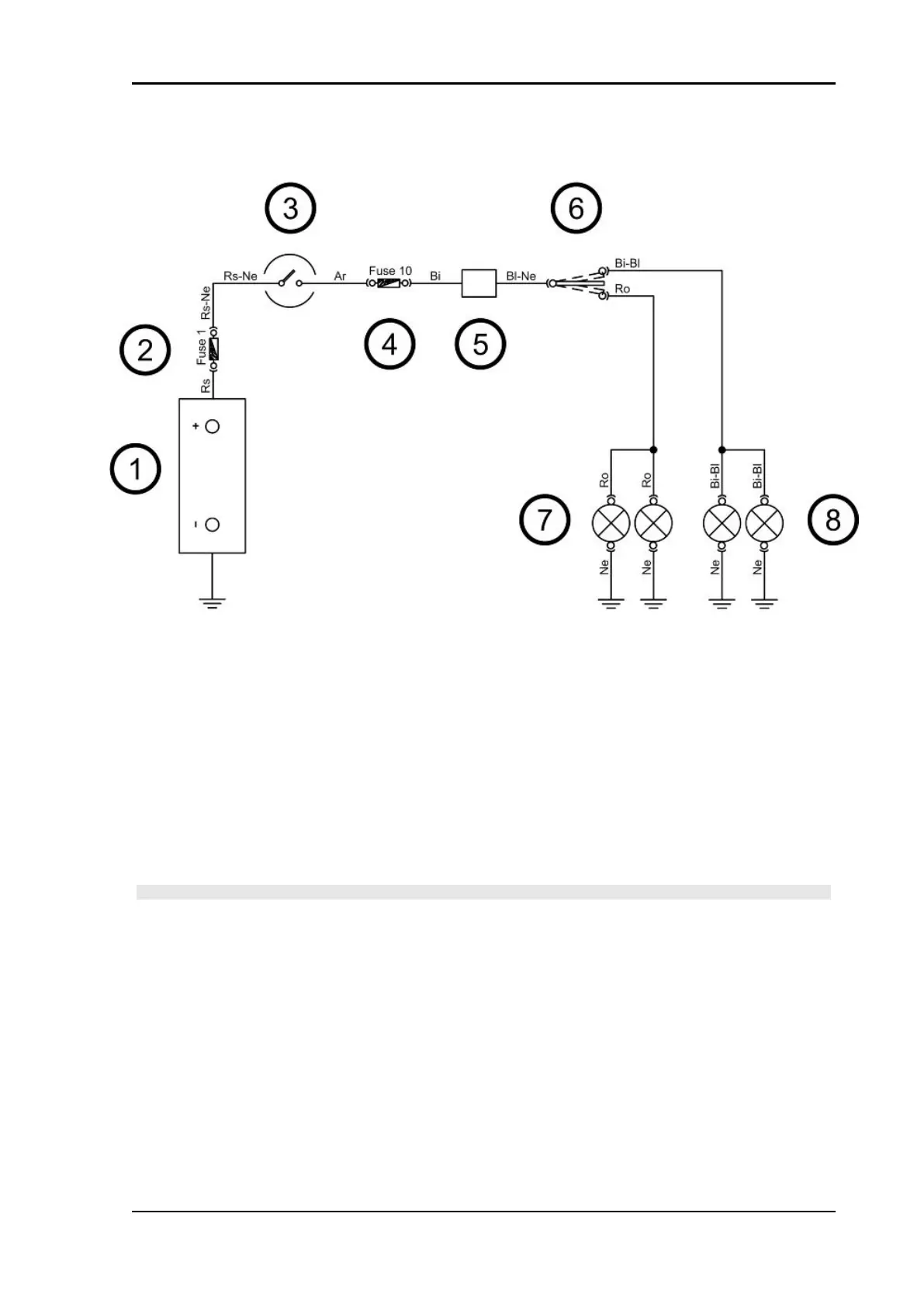
Turn signals system check
KEY
1. Battery
2. Fuse No. 1
3. Key switch contacts
4. Fuse No. 10
5. Turn indicator control device
6. Turn indicator switch
7. LH turn indicators
8. RH turn indicators
WARNING
ALL CONTINUITY TESTS MUST BE CARRIED OUT WITH THE CORRESPONDING CONNECTORS
DISCONNECTED.
1) Check the working order of bulbs.
2) Check fuses No. 1 and 10 and the key switch contacts.
3) Check if there is intermittent voltage between the Blue-Black cable of the turn indicator control device
and the ground connection.
4) If there is no voltage, check that the wiring is not interrupted.
5) Check the turn indicator switch.
6) Check that the Blue-Black cable between the turn indicator control device and the turn indicator switch
is not interrupted.
Beverly Tourer 300 i.e. Electrical system
ELE SYS - 95