Home
Piper
Aircrafts
Lance II
Piper Lance II User Manual
4
of 1
of 1 rating
568 pages
Give review
Manual
Specs
To Next Page
To Next Page
To Previous Page
To Previous Page
Loading...
1.
When
the
Final
timing
check
is
done,
back
the
engine
up
approximately
10
degrees;
then
carefully
bump
the
engine
forward
and
observe
the
position
that
the
breakers
open.
m.
Repeat
Step
k
if
necessary
until
conditions
of
Step
1
are
met.
If
the
late
breaker
8-31.
MAGNETO
TIMING
PROCEDURE
(INTERNAL
TIMING).
a.
Remove
magneto
cover.
b.
Loosen
flange
clamps
and
remove
magneto
from
engine.
breaker
opens
first.
m.
Repeat
Step
k
if
necessary
until
conditions
of
Step
1
are
met.
If
the
late
breaker
opens
more
than
3
degrees
from
the
early
one,
the
internal
timing
of
the
magneto
must
be
rechecked.
(Refer
to
Internal
Timing,
Paragraph
8-31.)
n.
Torque
the
magneto
securing
clamps
to
assembly
inch-pounds.
Recheck
timing
once
more
and
if
satisfactory
disconnect
the
timing
light
and
remove
the
adapter
leads.
o.
Reinstall
the
plugs
in
the
timing
inspection
holes
and
torque
to
12-15
inch-pounds.
Loosely
install
the
harness
with
clamps
and/or
brackets.
a.
Remove
magneto
cover.
b.
Loosen
flange
clamps
and
remove
magneto
from
engine.
c.
Check
condition
of
points;
replace
if
necessary.
d.
Rotate
the
magneto
drive
shaft
until
a
main
cam
lobe
touches
the
follower
of
the
left
main
breaker
assembly
and
adjust
the
breaker
points
to
an
initial
opening
of
.016
inch.
Wire
feeler
gauge
is
recommended.
e.
Adjust
right
main
breaker
contact
assembly
to
an
initial
point
opening
of
.016
inch
just
as
in
Step
d.
f.
Fixed
contact
support
may
be
bent
to
adjust
clearance.
If
support
is
bent,
main
breaker
contact
must
be
rechecked.
Torque
breaker
securing
screws
to
20-25
inch-pounds.
Issued:
1/3/78
POWER
PLANT
2B7
LANCE
H
SERVICE
MANUAL
318
320
Table of Contents
Table of Contents
3
Schematic Diagram of RSA Fuel Injection System
7
Electrical Symbols
11
Landing Gear
13
Scope of Manual
13
Brake System
14
Flight Controls
14
Fuel System
14
Instrument and Autopilot System
14
Section II Handling and Servicing
15
Handling and Servicing
15
Dimensions
17
Serial Number Plate
17
Ia17
17
Station Reference Lines
17
Tools and Test Equipment
25
Torque Requirements
25
Installation of Flexible Hose Assemblies
31
Ground Handling
45
General
45
Leveling
46
Mooring
47
Parking
48
Taxiing
49
External Power Receptacle
49
Fuel System
50
1C2
50
Filling Fuel Tanks
50
Draining Fuel System
51
Servicing
50
General
50
Brake System
51
Servicing Brake System
51
Filling Brake Cylinder Reservoir
51
Draining Brake System
51
Hydraulic System
54
Servicing Hydraulic System
54
1C6
54
Servicing Hydraulic Pump Reservoir
54
Landing Gear System
54
Servicing Landing Gear
54
Inspection
77
Sectionv Surfacecontrols
131
Wing
131
Surface Controls
132
Description
132
Introduction
132
Control Column Assembly
138
Removal of Control Column Assembly
138
Aileron Controls
139
Removal of Aileron Control Cables
139
Installation of Aileron Control Cables
140
Removal of Aileron Bellcrank Assembly
142
Installation of Aileron Bellcrank Assembly
143
Rigging and Adjustment of Aileron Controls
143
Stabilator Controls
147
Removal of Stabilator Control Cables
147
Installation of Stabilator Control Cables
148
Rigging and Adjustment of Stabilator Controls
149
Stabilator Trim Controls
153
Removal of Stabilator Trim Assembly (Forward)
153
Installation of Stabilator Trim Assembly
154
Removal of Stabilator Trim Controls (Aft)
155
Installation of Stabilator Trim Controls (Aft)
155
Rigging and Adjustment of Stabilator Trim
155
Rudder and Steering Pedal Assembly
156
Installation of Rudder and Steering Pedal Assembly
157
Rudder Controls
159
Removal of Rudder Control Cables
159
Installation of Rudder Control Cables
160
Rigging and Adjustment of Rudder Controls
162
Rudder Trim Controls
162
Removal of Rudder Trim Controls
162
Sectionvi Hydraulic System
181
Description
181
Hydraulic System
181
Assembly of Hydraulic Pump
192
Installation of Hydraulic Pump
193
Gear Back-Up Extender Actuator Assembly
193
Removal of Gear Back-Up Extender Actuator Assembly
193
Installation of Gear Back-Up Extender Actuator Assembly
194
Check and Adjustment of Gear Back-Up Extender Actuator
196
Nose Gear Actuating Cylinder
199
Removal of Nose Gear Actuating Cylinder
199
Disassembly of Nose Gear Actuating Cylinder
200
Cleaning, Inspection and Repair of Nose Gear Actuating Cylinder
201
Assembly of Nose Gear Actuating Cylinder
201
Installation of Nose Gear Actuating Cylinder
201
Main Gear Actuating Cylinder
201
Removal of Main Gear Actuating Cylinder
201
Disassembly of Main Gear Actuating Cylinder
203
Cleaning, Inspection and Repair of Main Gear Actuating Cylinder 1111
203
Assembly of Main Gear Actuating Cylinder
203
Installation of Main Gear Actuating Cylinder
204
Hydraulic Lines
204
Sectionvii Landing Gear and Brake System
219
Description
221
Introduction
221
Landing Gear System
225
Nose Landing Gear System
225
Disassembly of Nose Gear Oleo
225
Cleaning, Inspection and Repair of Nose Gear Oleo
226
Assembly of Nose Gear Oleo
226
Removal of Nose Landing Gear
228
Cleaning, Inspection and Repair of Nose Landing Gear
230
Installation of Nose Landing Gear
230
Adjustment of Nose Landing Gear
236
Alignment of Nose Landing Gear
237
Removal of Nose Gear Door Assembly
238
Cleaning, Inspection and Repair of Nose Gear Door Assembly
239
Installation of Nose Gear Door Assembly
240
Adjustment of Nose Gear Doors
240
Main Landing Gear System
240
Disassembly of Main Gear Oleo
240
Cleaning, Inspection and Repair of Main Gear Oleo
245
Assembly of Main Gearoleo
245
Removal of Main Landing Gear
249
Cleaning, Inspection and Repair of Main Landing Gear
250
Installation of Main Landing Gear
251
Adjustment of Main Landing Gear
252
Alignment of Main Landing Gear
253
Cleaning, Inspection and Repair of Main Gear Door Assembly
256
Installation of Main Gear Door Assembly
256
Troubleshooting
225
Landing Gear Limit Switches
256
Adjustment of Nose Gear up Limit Switch
257
Adjustment of Main Gear down Limit Switch
258
Adjustment of Landing Gear Safety Switch (Squat Switch)
259
Adjustment of Gear Back-Up Extender Actuator Switch
259
Wheel Brake Assembly
269
Brake Master Cylinder (Hand/Parking Brake)
272
Brake Cylinder (10-27) (Toe Brake)
275
Brake Cylinder (1700) (Toe Brake)
275
Brake Cylinder (10-30) (Toe Brake)
278
Fuel System
291
2D12
291
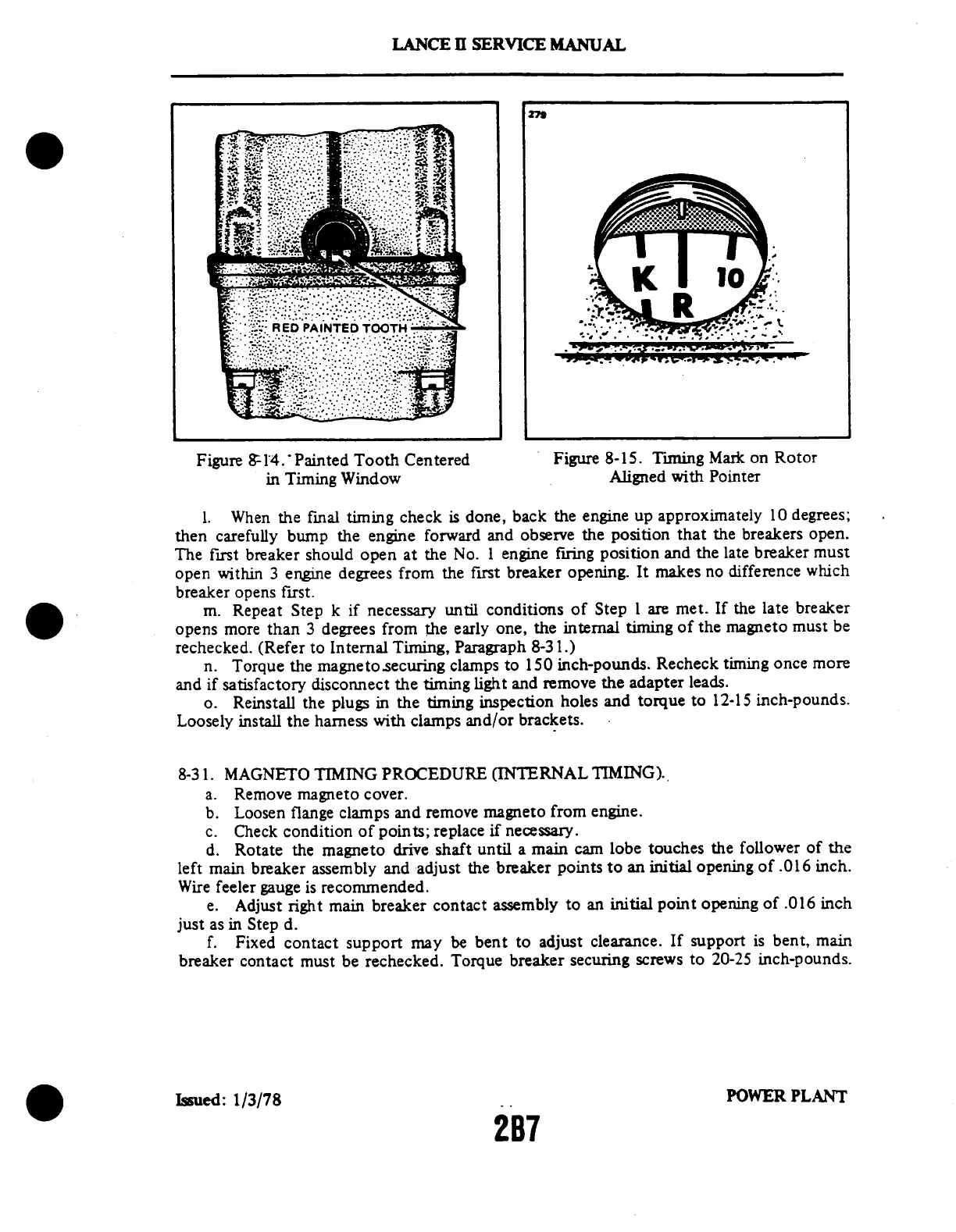
Painted Tooth Centered in Timing Window
292
Timing Mark on Rotor Aligned with Pointer
292
Timing Light Connected to Magneto and Breakers
292
Checking Flyweight to Stop Pin Clearance
292
Checking Impulse Coupling for Magnetization
292
Orientation of Springs in Coupling Body
292
Checking Harness Lead Continuity
292
Checking Harness Lead Insulation Resistance
292
Removing Spring from Lead Assembly
292
Electrical System Troubleshooting
295
Temperature Pressure Chart
295
Aluminum Tubing Torque
295
Compressor Oil Charge
295
Oxygen System Component Limits
295
Propeller Installation
299
Propeller Blade Minor Repair
300
Propeller Governor
303
Engine Installation
306
Adjustment of Engine Controls
308
Fuel Injector
311
Fuel-Air Bleed Nozzle
313
Height of Spring in Distributor Block Tower
314
Contact Points
315
Engine Timing Marks
315
Timing Light Connected to Magneto
317
Timing Marks on Magneto Rotor
318
Cam End View of Magneto
322
Removing Impulse Coupling
323
Stop Pin Installation Dimension
324
Checking Flyweight Axial Wear with Drill Shank
325
Checking Flyweight Radial Wear with Gauge
325
Points of Coupling Body Wear
326
Acceptable and Deformed Coupling Springs
326
Lifting Inner End of Spring
328
Modified Pliers
330
Assembly Tool
331
Using Assembly Tool
331
Ferrule Positioned under Braid
331
Hydraulic System
291
Landing Gear and Brake System
291
1J3
291
Aerofiche Card no
291
Power Plant (Pa-32Rt-300) 2A8 Viiia
291
Power Plant (Pa-32Rt-300T) 2C8
291
Structure
291
Vsurface Controls
291
General/Engine
386
Engine
386
General
386
Airspeed Indicator
403
Troubleshooting
404
Troubleshooting
406
Manifold Pressure Gauge
407
Troubleshooting
407
Tachometer Indicator
407
Troubleshooting
408
Troubleshooting
409
Fuel Pressure Gauge (PA-32RT-300)
409
Troubleshooting
410
Turn and Bank Indicator
411
Troubleshooting
411
Electrical Instruments
412
Fuel Quantity Indicator
412
Troubleshooting
412
Oil Temperature Indicator
413
Electrical System
419
General
420
Index - Electrical System Schematics
422
Ammeter
443
General
455
Electrical System Component Loads
469
Electrical Symbols
487
Electrical Wire Coding
488
Electronics
501
Heating and Ventilating
512
Accessories and Utilities
520
4
Based on 1 rating
Ask a question
Give review
Questions and Answers:
Need help?
Do you have a question about the Piper Lance II and is the answer not in the manual?
Ask a question
Piper Lance II Specifications
General
Manufacturer
Piper Aircraft
Max Takeoff Weight
3, 600 lb (1, 633 kg)
Crew
1
Horsepower
300 hp
Seats
6
Length
27 ft 7 in (8.41 m)
Capacity
5 passengers
Related product manuals
Piper Cherokee Arrow II
189 pages
Piper CHEROKEE WARRIOR II
282 pages
Piper SARATOGA II HP PA-32R-301
470 pages
Piper Dakota
616 pages
Piper COMANCHE
61 pages
Piper PA-28-180
80 pages
Piper Warrior III
1104 pages
Piper Cherokee 140
62 pages
Piper CHEROKEE 180
73 pages
Piper CHEROKEE 180 C
80 pages
Piper Arrow PA-28R-201
470 pages
Piper Cherokee SIX 300
854 pages

 Loading...


