23
Laboratory Oscillator Interplay
Overview
The interplay between the two laboratory oscillators can be harnessed in several ways. Ring
modulation, bit crushing, frequency modulation, and bi-directional hard sync are all available to
create the widest possible range of sounds.
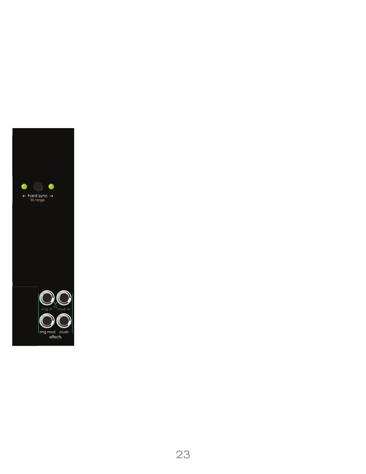
Hard Sync
Hard Sync enables a “following” oscillator’s period to be reset, or retriggered by a “lead” oscillator.
Depending on the frequency relationship of the two oscillators and how the following oscillator is
modulated, the resulting audio can emphasize higher harmonics while a base pitch is still present
and discernible.
Hard Sync is set using the [HARD SYNC BUTTON], pressing this button will cycle between each
oscillator synced to the other, or bidirectional simultaneous sync, where both oscillators are
actively resetting each other.
Ring Modulator
A ring modulator outputs the sum and difference of Laboratory Oscillator 1 sine wave and modu-
lation source. Depending on the frequency relationship of the two signals, ring modulation can
emphasize harmonics or create harsh metallic sounds. The seed wave is patched through the x
input and the modulation source is patched through the y input of the ring modulator circuit. Ring
Modulation can act as a VCA if modulated with an envelope or LFO.
The Sine wave output of Oscillator 1 is always the audio input to the ring modulator, and its level is
modulated by Oscillator 2, or an external signal patched to [RING IN JACK]. The [RING MOD JACK]
output jack is the result of that modulation.
Bit Crusher
Bit crushing effectively limits the rate at which an audio signal “updates” to a new voltage. It might
be helpful to think of it as a sample and hold circuit that can handle audio rate signals.
The main output of Oscillator 1 is always the audio input to the bit crusher, and by default
Oscillator 2’s seed out is our clock signal. Plugging a patch cable into the [CRUSH IN] jack will
replace Oscillator 2 as the clock signal.
The processed audio can sound aliased, downsampled, or reminiscent of low-resolution digital
audio.
Oscillator Effects Input Jacks :
[RING IN JACK] Ring modulator circuit’s modulator input. Normaled to Oscillator 2 sine.
[CRUSH IN JACK] Bit Crush circuit’s clock input. Normaled to Oscillator 2 seed.
Oscillator Effects Output Jacks :
[RING MOD JACK] Ring modulator output.
[CRUSH JACK] Bit crusher output.
3 Voltage Lab 2 Voice Modules