25
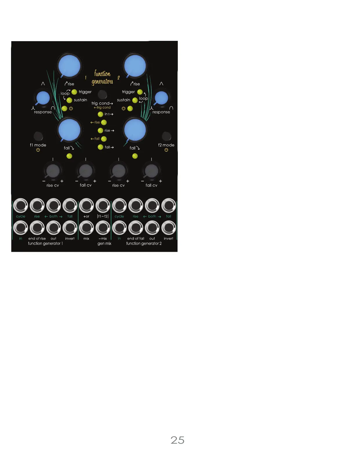
Trigger Conditions
The pair of Function Generators can be used independently or linked together to create complex modulations. Trigger
Conditions determine when the Function Generators trigger each other.
Assign how Function Generator 1 triggers Function Generator 2 by pressing the [TRIG CONDITION BUTTON]
F1 Trigger Options
Trigger F2 when F1 receives a trigger
Trigger F2 at F1 end of rise
Trigger F2 at F1 end of fall
Or any combination of the above
Assign how Function Generator 2 triggers Function Generator 1 by pressing the [EDIT BUTTON] + [TRIG CONDITION BUTTON]
F2 Trigger Options
Trigger F1 at F2 end of rise
Trigger F1 at F2 end of fall
Trigger F1 at F2 end of rise and end of fall
Or any combination of the above
Function Generators
Trigger Mode
Trigger Mode can be used to create a two stage attack
(rise), decay (fall) envelope, gate signal delay or clock
divider. The internal circuitry responds differently than
sustain mode when triggered. A gate or CV signal
patched into the [IN JACK] over two volts initiates the rise
stage, and the function generator will increase over time
to 5v. Once the function generator reaches 5v, the fall
stage is initiated, and the output will drop over time to 0v.
Some CV signals may trigger the Function Generator as
long as the waveform has a sharp enough rising slope. In
trigger mode, the function generator will not retrigger
during the rise stage, however the envelope will retrigger
during the fall mode. This quirk allows the function
generator to work as a clock divider by adjusting the rise
stage to skip over or miss a set number of incoming gate
signals.
Loop Mode
Loop Mode is an extension of trigger mode and utilizes all
the same feature set. To create the loop, the function
generator uses the end of fall trigger created at the end
of the cycle to retrigger the rise creating a voltage
controllable low frequency oscillator or clock source.
3 Voltage Lab 2 Voice Modules