41
BT37 MarkII: Service Manual MA200606 1.0.0
Component replacement
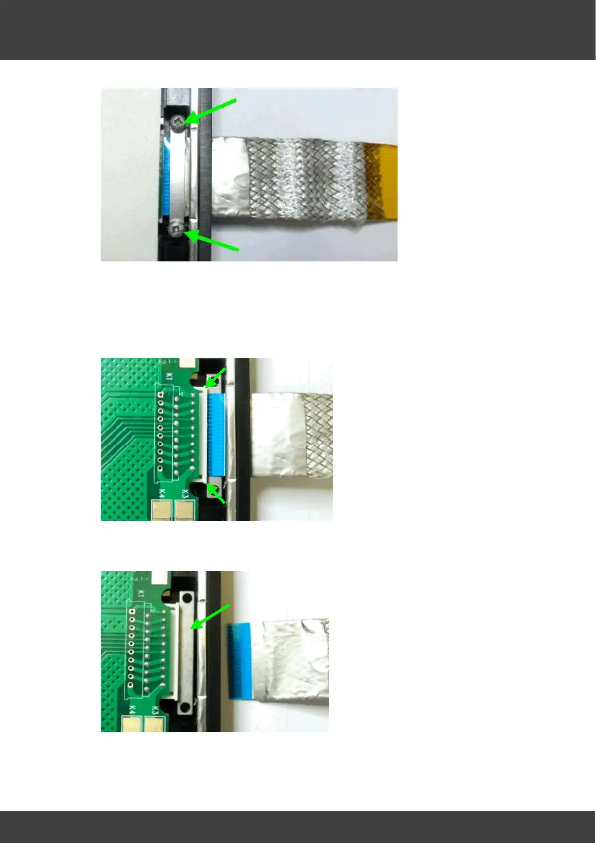
Fig.3. Clamping Bar Above FCC Cable. (Support bar not visible below cable)
6. Fold back the silicone insulating pad to access Cable connector.
7. Release the FCC connector cable locking mechanism and remove Ribbon Cable
Assembly. Cable should be pulled carefully away from board edge. Refer to Fig.4.
Fig 4. FCC Cable Locking Mechanism Released.
8. With Ribbon Cable Assembly removed, Support Bar now visible, Refer to Fig.5.
Fig.5. FCC Cable Support Bar.
9. Replacement FCC cable assembly should look as shown in fig.6.