56
BT37 MarkII: Service Manual MA200606 1.0.0
Component replacement
Refitting the humidifier assembly
9) Position the humidifier in the enclosure and secure it with the eight screws shown
circled in Fig.2
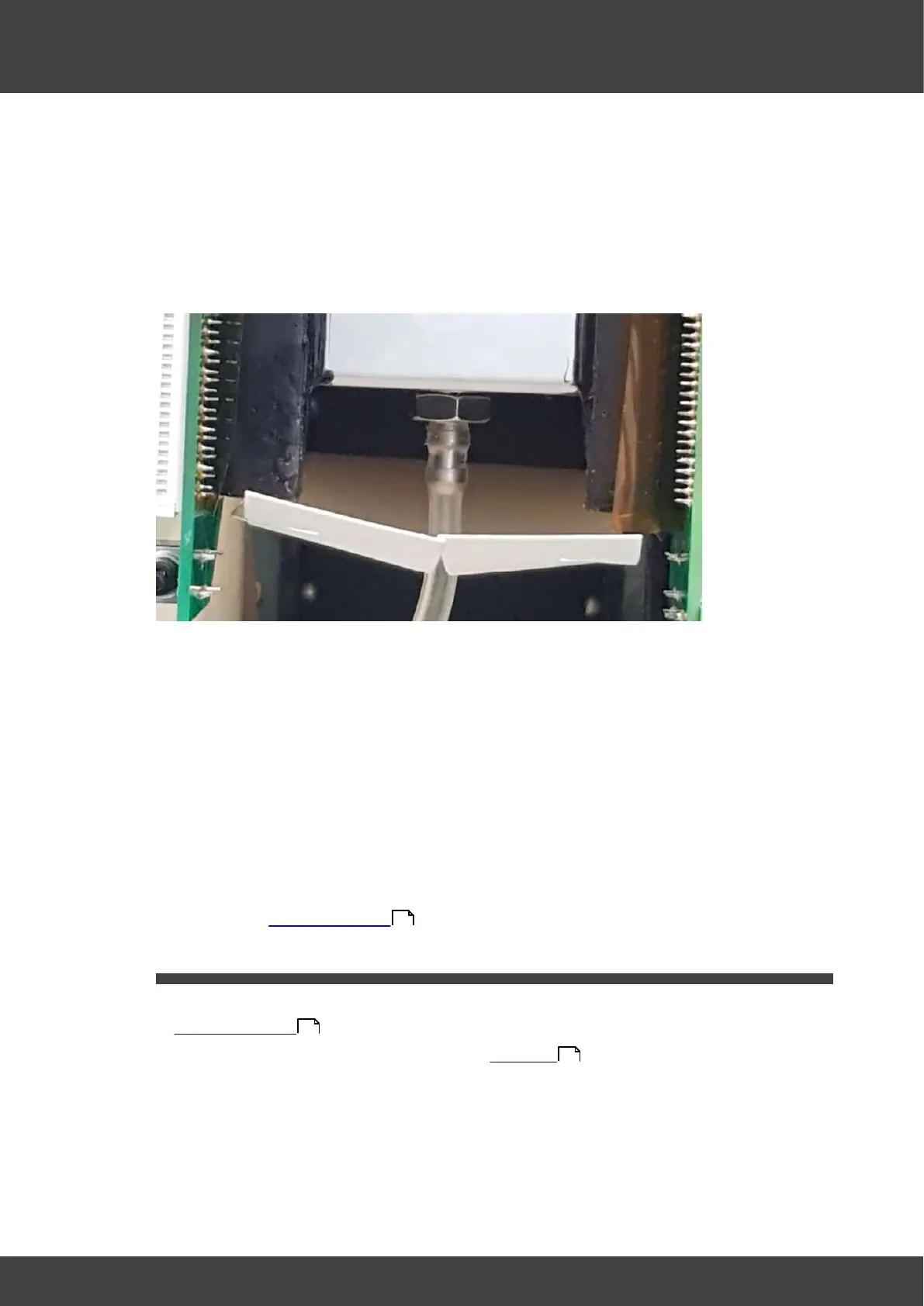
10) Push the tube from the mass flow meter onto the luer outlet port barb at the back of
the humidifier assembly as shown in Fig.3
Fig.3 showing humidifier asembly luer outlet port
11) Reconnect the fan cable, routing it round the back of the left humidifier board so that
it will not be trapped by the rear panel when it is re-fitted.
12) Reconnect the 20-way and 30-way FCC cables to the motherboard. The cable
orientation is with the cable contacts away from the humidifier pcb surfaces. Ensure
the FCC connector latches are fully engaged in order to firmly restrain the cables
within the connectors.
13) Remove the temporary insulation from the battery terminals. Connect the battery by
offering up the spade terminals and reverse_polarity_protection_bar as one complete
unit. It is important to refit the battery connections only when they are held in
position within the reverse_polarity-protection_bar. Never remove the spade
connectors from the bar to fit them.
14) Refit the left and right hand lid assemblies and rear panel of the incubator as
described in Opening the BT37 .
3.11 Left humidifier pcb
1) Remove the incubator rear panel and left and right lid assemblies as described in
Opening the BT37 .
2) Remove the humidifier assembly as detailed in Humidifier
3) Remove the left humidifier circuit board from the humidifier assembly by removing the
nuts, washers and screws shown in Fig.1
36
36
54