48
BT37 MarkII: Service Manual MA200606 1.0.0
Component replacement
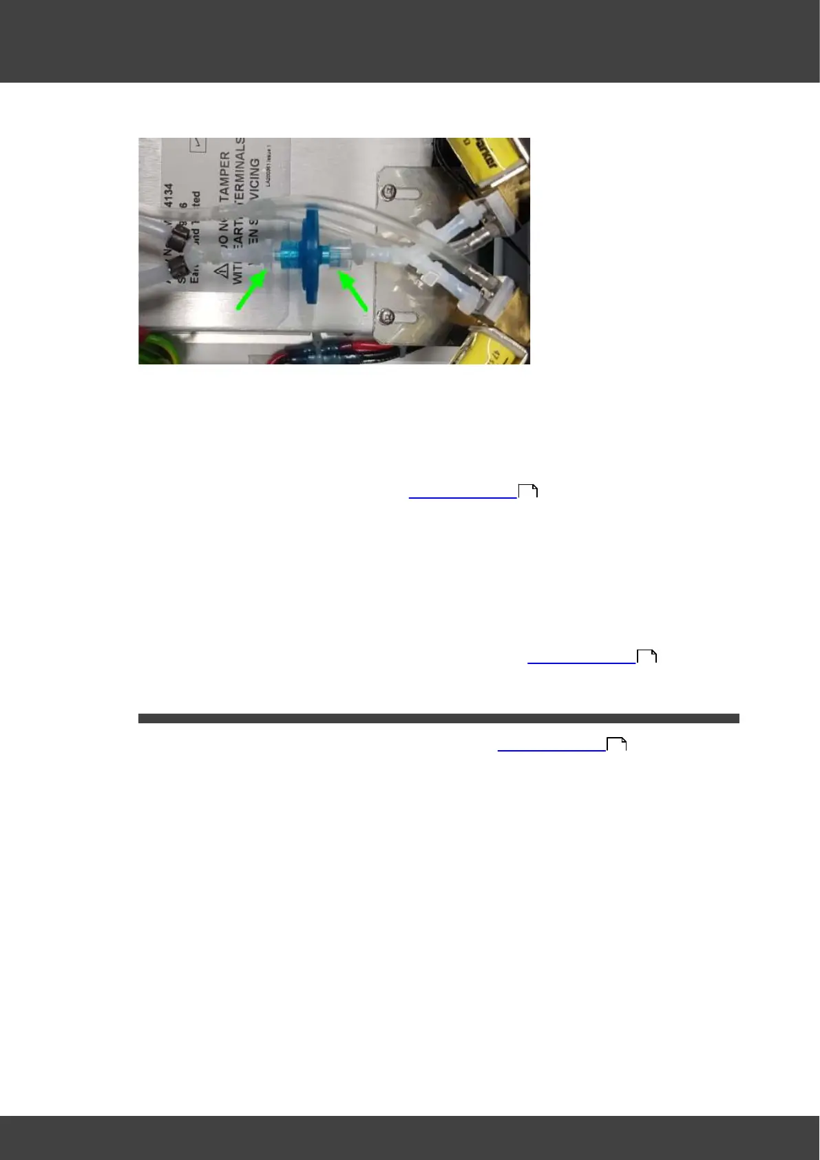
Fig.2 showing the two luer clamps
3) Fit the new filter unit and secure tightly with the two luer clamps, ensuring that the "Y"
tube to the rear panel is orientated horizontally when the clamps are tightened. If
necessary loosen the right hand clamp shown in Fig.1 to adjust the orientation and
then re-tighten.
4) Refit the lid and rear panel as described in Opening the BT37 .
5) Fit new filter unit by following the same method as described above but in the reverse
sequence. Secure tightly both female and male luer connector until you feel a
significant increase in resistance.
Note over tightening will cause the connector or the filter to crack. Ensure that the "Y"
tube to the rear panel is orientated horizontally when the luer connectors are
tightened, If necessary, while holding the female connector, rotate the bulkhead
assembly around the barb connector of the female connector.
6 ) Refit the right lid assembly and the rear panel as described in Opening the BT37 .
3.6 Fan
1) Remove the rear panel from the incubator as described in Opening the BT37 .
2) Release the fan from its anti-vibration mounts by gently pulling it away one corner at a
time from the rear panel.
3) Fit the new fan and anti-vibration mounts to the back panel, ensuring the cable exit is
towards the bottom of the rear panel (Fig.1), and the air direction as indicated by the
flow arrow on the body of the fan is into the incubator (Fig.2).
36
36
36