57
BT37 MarkII: Service Manual MA200606 1.0.0
Component replacement
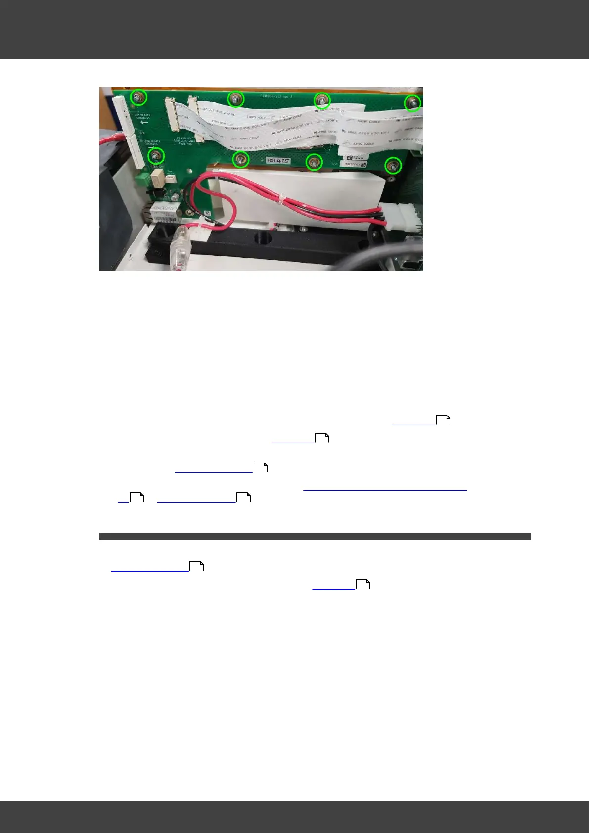
Fig.1 location of nuts and washers to remove
4) There is an insulating kapton film sheet between the humidifier printed circuit board
and the humidifier assembly. Ensure this is left in place when the board is removed.
5) Check that the thermistor well on the humidifier side wall is sufficiently filled with Dow
Corning 340 heat sink compound so that the 0805 thermistor on the back of the
printed circuit board will make good thermal contact to the side wall plate.
6) Position the replacement left humidifier pcb over the fixing studs, ensuring the kapton
film sheet is sandwiched between the circuit board and the humidifier metalwork.
7) Refit the nuts and washers and screws that were removed at step 3).
8) Fit the humidifier assembly back into the enclosure as detailed in Humidifier
9) Re connect the battery as detailed in Humidifier
10) Refit the left and right hand lid assemblies and rear panel of the incubator as
described in Opening the BT37 .
11) Calibrate the humidifier unit as described in Calibration using automatic calibration
kit or Manual calibration .
3.12 Right humidifier pcb
1) Remove the incubator rear panel and left and right lid assemblies as described in
Opening the BT37 .
2) Remove the humidifier assembly as detailed in Humidifier
3) Remove the right humidifier circuit board from the humidifier assembly by removing the
nuts, washers and screws shown in Fig.1
54
54
36
136 154
36
54