75
BT37 MarkII: Service Manual MA200606 1.0.0
Component replacement
19) Remove the temporary insulation from the battery terminals. Connect the battery by
offering up the spade terminals and reverse_polarity_protection_bar as one complete
unit. It is important to refit the battery connections only when they are held in
position within the reverse_polarity-protection_bar. Never remove the spade
connectors from the bar to fit them.
20) Refit the left and right hand lid assemblies and rear panel of the incubator as
described in Opening the BT37 .
21) Load the latest software into the device as described in Programming the BT37
MarkII .
22) Calibrate the unit as described in Calibration using automatic calibration kit or
Manual calibration .
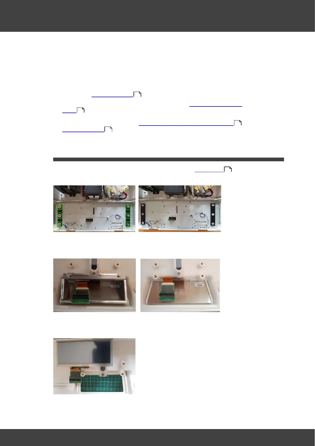
3.17 Display
1) To access the display follow the instructions to remove the Motherboard .
2) Remove screws and washers to release the metal panel, see Fig.1a & Fig.1b.
Fig.1a Front plate fixings Fig.1b Front plate removed
3) Remove the EMC tunnel, see Fig.2a & Fig.2b.
Fig.2a EMC tunnel Fig.2b EMC tunnel removed
3) Lift out the display, see Fig.3.
Fig.3 Display removed
4) Assembly is the reverse of disassembly.
36
106
136
154
71