74
BT37 MarkII: Service Manual MA200606 1.0.0
Component replacement
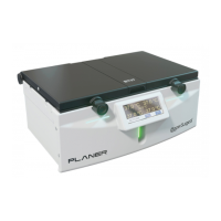
Fig.10 Remove screws to detach circuit board from front panel
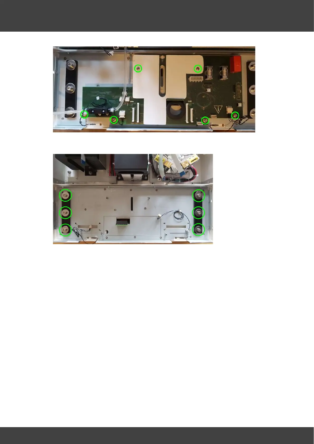
Fig.11 View of the front panel with the motherboard removed
13) Screw the new board and insulation plate into position on the front panel metalwork.
14) Offer the front panel up to the incubator and fit the power supply connector, the two
gas valve connectors, the pressure relief valve and the four flat cables. Insert the flat
cables fully into their connectors and then fully engage the connector latches in
order to clamp the flat cables.
15) Whilst fitting each tube it is important to support the body of the mass flow
meter to provide the opposing force, i.e. do not strain the connecting leads
to the motherboard. Do not use any lubrication when fitting the tubes, they
must remain dry and oil free. Remove the protective caps from the mass flow
meter and carefully push the gas supply tubes fully onto the inlet and outlet ports.
The inlet port is the left hand port as viewed in Fig.10 and connects to the valve
assembly. The right hand port is the outlet and connects to the luer connector
installed in the base of the humidifier chamber.
16) Secure the tubes to the mass flow meter ports with tie wraps.
17) Refit the front panel to the incubator enclosure with the side and base screws that
were removed at step 5.
18) Tighten the humidifier assembly screws that were loosened at step 4.
 Loading...