73
BT37 MarkII: Service Manual MA200606 1.0.0
Component replacement
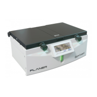
Fig.6 Pressure relief valve
10) Slide the flat cable connector latches to the released position and remove the four
flat cables from the motherboard.
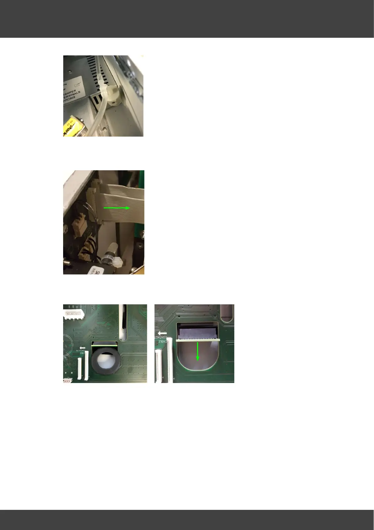
11) Remove the rubber seal from the PCB and disconnect the display interface PCB.
Fig.8 Rubber seal Fig.9 Display connector
12) Remove the screws that attach the motherboard and insulation plate to the front
panel as shown in Fig.10
 Loading...