72
BT37 MarkII: Service Manual MA200606 1.0.0
Component replacement
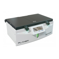
Fig.2 Remove screws along both sides and the base
6) Partially separate the front panel assembly from the case being careful not to pull on
any of the attached cables or tubes.
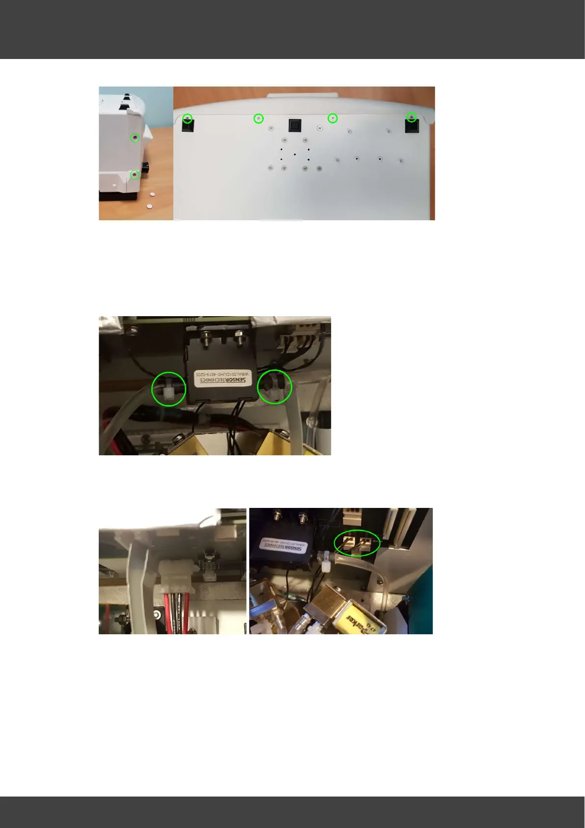
7) Carefully cut and remove the tie wraps that secure the gas supply tubes to the mass
flow meter MFM1 on the motherboard, and remove the tubes whilst supporting the
mass flow meter.
Fig.3 Flow meter tie wraps
8) Remove the power supply connector and the two gas valve connectors from the
motherboard see Fig.4 & Fig.5.
Fig.4 Power connector Fig.5 Gas valve connectors
9) Remove flow meter tube from the pressure relief valve see Fig.6.
 Loading...