50
BT37 MarkII: Service Manual MA200606 1.0.0
Component replacement
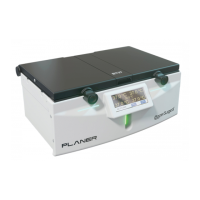
Fig.1 IEC inlet with fuse holder partially ejected
fit new fuse and slide the fuse tray fully back into to IEC inlet
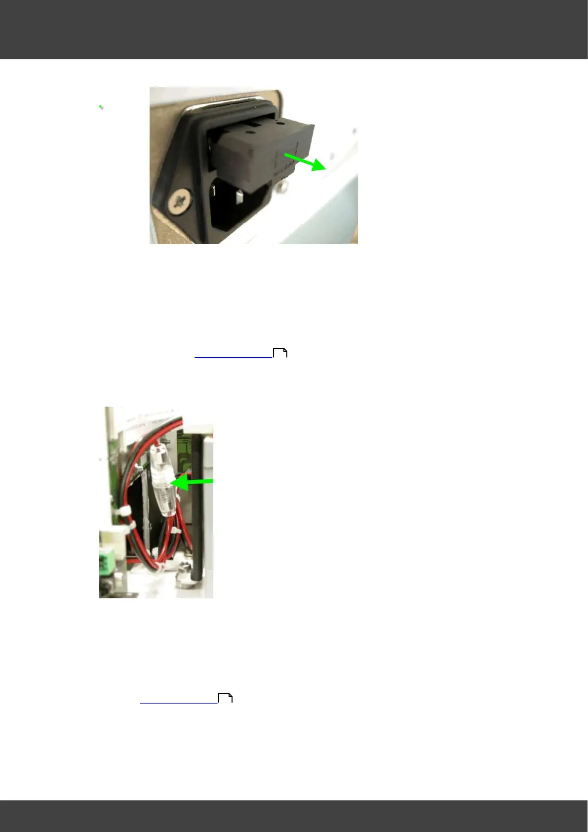
To replace the battery fuse in the battery positive lead:
Disconnect and remove the mains inlet cable from the IEC inlet socket
Remove the rear panel of the incubator and the left hand lid assembly as
described in Opening the BT37
Insulate the exposed battery terminals with insulating tape before
proceeding.
Fig.3 fuseholder in battery positive lead
Remove the temporary insulation on the battery terminals then re-connect the
battery by offering up the spade terminals and reverse_polarity_protection_bar
as one complete unit. It is important to refit the battery connections only when
they are held in position within the reverse_polarity-protection_bar as shown if
Fig.2. Never remove the spade connectors from the bar to fit them.
Refit the left hand lid assembly and rear panel of the incubator as described in
Opening the BT37 .
To replace the power supply fuses on the motherboard:
Disconnect and remove the mains inlet cable from the IEC inlet socket
36
36