52
BT37 MarkII: Service Manual MA200606 1.0.0
Component replacement
4) Carefully lift the gas valve bracket and valve assembly out of the chamber as far as
possible to give access to the valve plate manifold screws.
5) Identify the purge or bleed gas valve to be replaced by tracing the valve connecting
leads to the motherboard. The purge and bleed connectors are identified on the
motherboard.
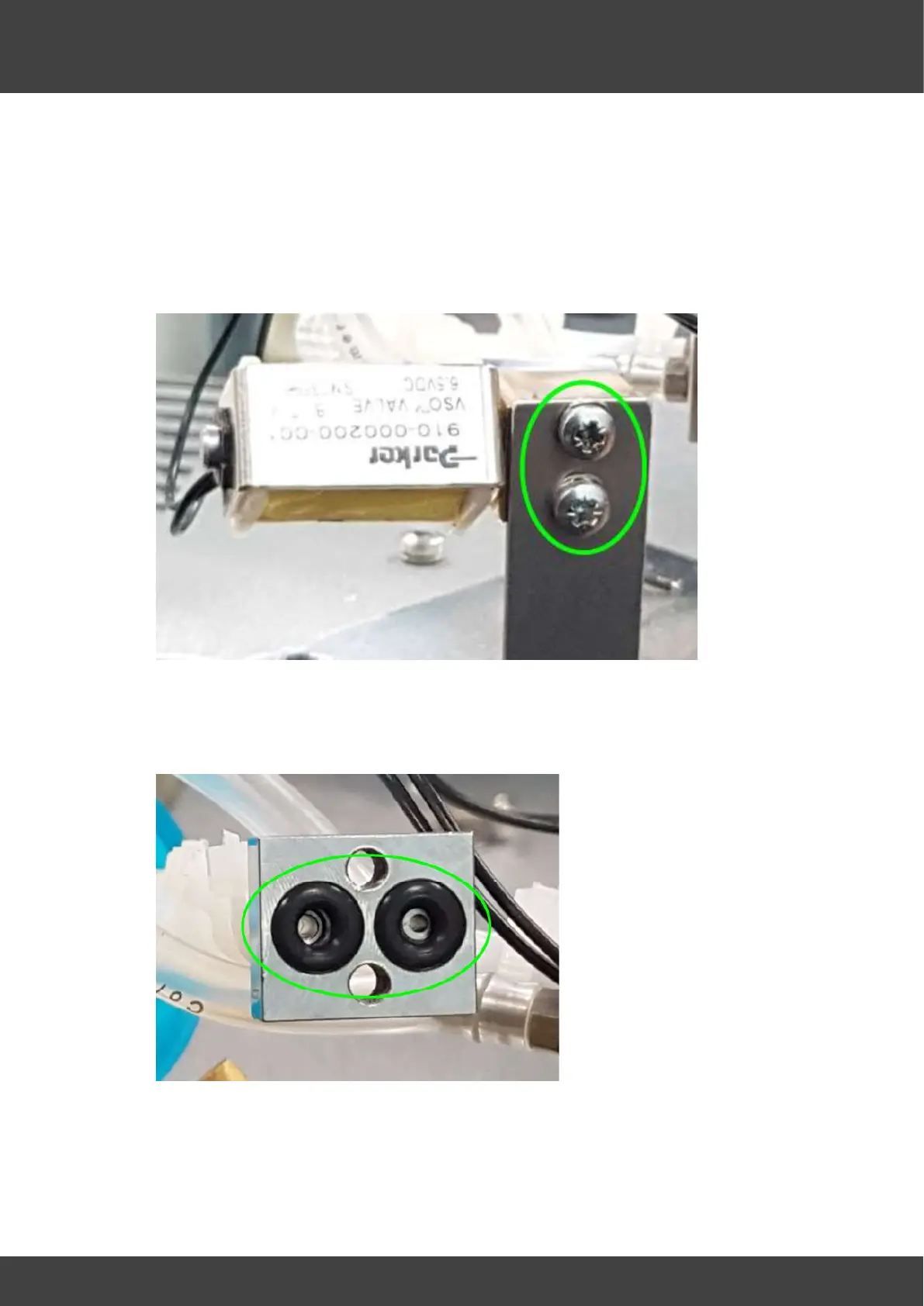
6) Remove the two screws that secure the gas valve to the bracket manifold, as shown
in Fig.2.
Fig.2 showing the 2 screws that secure the gas valve to the bracket manifold
7) Separate the valve from the manifold to expose the two O-ring seals fitted in the
manifold as shown in fig.3
Fig.3 showing O-rings in manifold
8) Fit two new O-ring seals.
Securing and positioning the gas valve assembly