70
BT37 MarkII: Service Manual MA200606 1.0.0
Component replacement
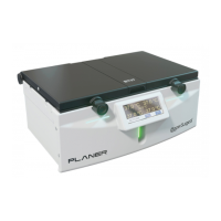
Fig.5 Slide insulating boot back along cable
7) Remove the spade connections from the old IEC inlet filter.
8) Unscrew and remove the old IEC inlet filter from the rear panel.
9) Screw the new IEC inlet filter into position on the rear panel.
10) Fit the spade connections to the new IEC inlet filter, observing the connection
annotations marked on the body of the inlet.
11) Slide the insulating boot back over the body of the IEC inlet filter as shown in Fig.5
12) Refit the outer supply cover and secure it to the inner cover with the screws and
washers removed at step 5
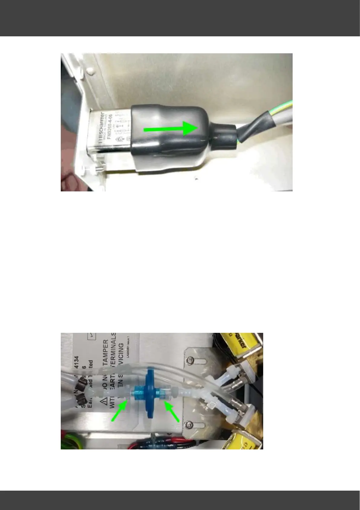
13) Refit the rear panel gas manifold assembly to the internal gas filter and securely
tighten the two luer clamps, ensuring that the "Y" tube to the rear panel is orientated
horizontally when the clamps are tightened. If necessary loosen the right hand luer
connector to make any adjustment, then re-tighten securely. See Fig.6.
Fig.6 luer connectors securing internal gas filter