Chapter E - DIMAX3 DIGITAL SYSTEM ADJUSTMENT
E-26 Planmeca Proline CC panoramic x-ray
Technical Manual
Take an exposure. The images of 23 balls should appear on the image. They should be round,
all the same size, and evenly spaced.
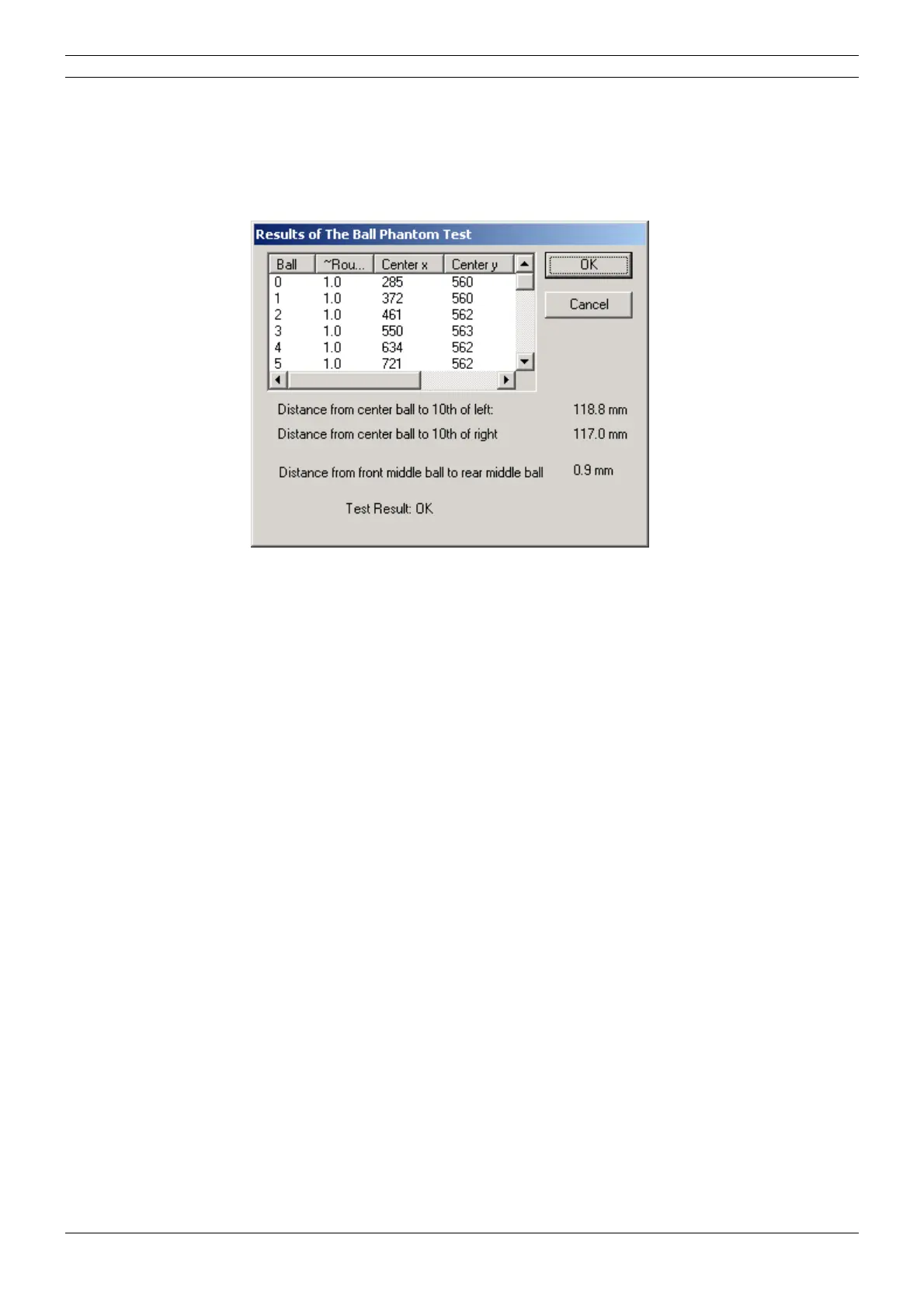
Also the Results of the ball phantom test window appears. In this window the distances from the
center of the middle ball to the center of the tenth ball on the right and left side, and the distance
from the center of the middle ball to the center of the rear middle ball are given.
Figure 49
The outermost balls on the left and right sides should appear symmetrically. If the distance from
the center of the middle ball to the center of the tenth ball on the right side differs more than 2mm
from the corresponding distance on the left side, the rotation start limit must be adjusted (in the
same way as in the film-based panoramic x-ray, see section
“Rotation limits” on page D-23).
Note, that the adjustment of the patient positioning mechanism must be performed first.
The distance from the center of the middle ball to the center of the rear middle ball should be less
than 2mm. If the distance is not correct you will have to adjust the position of the patient position
-
ing mechanism (see section “Patient positioning mechanism adjustment” on page E-31).