Chapter E - DIMAX3 DIGITAL SYSTEM ADJUSTMENT
E-36 Planmeca Proline CC panoramic x-ray
Technical Manual
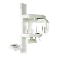
Measure the distance between the line on the alignment ruler and the x-line on the ball phantom
(
Fig. 64). The distance must be less than 1mm.
Figure 64 180° position
If the distance between the line on the alignment ruler and the x-line on the ball phantom is more
than 1mm, the sensor head position must be adjusted. Adjust the sensor head towards the ball
phantom’s x-line until the distance is less than 1mm according to the instructions given in section
“Adjusting the position of the sensor head” on page E-36. Correct only half of the deviation, so
that the deviation will be the same in both the 180° and 0° positions.
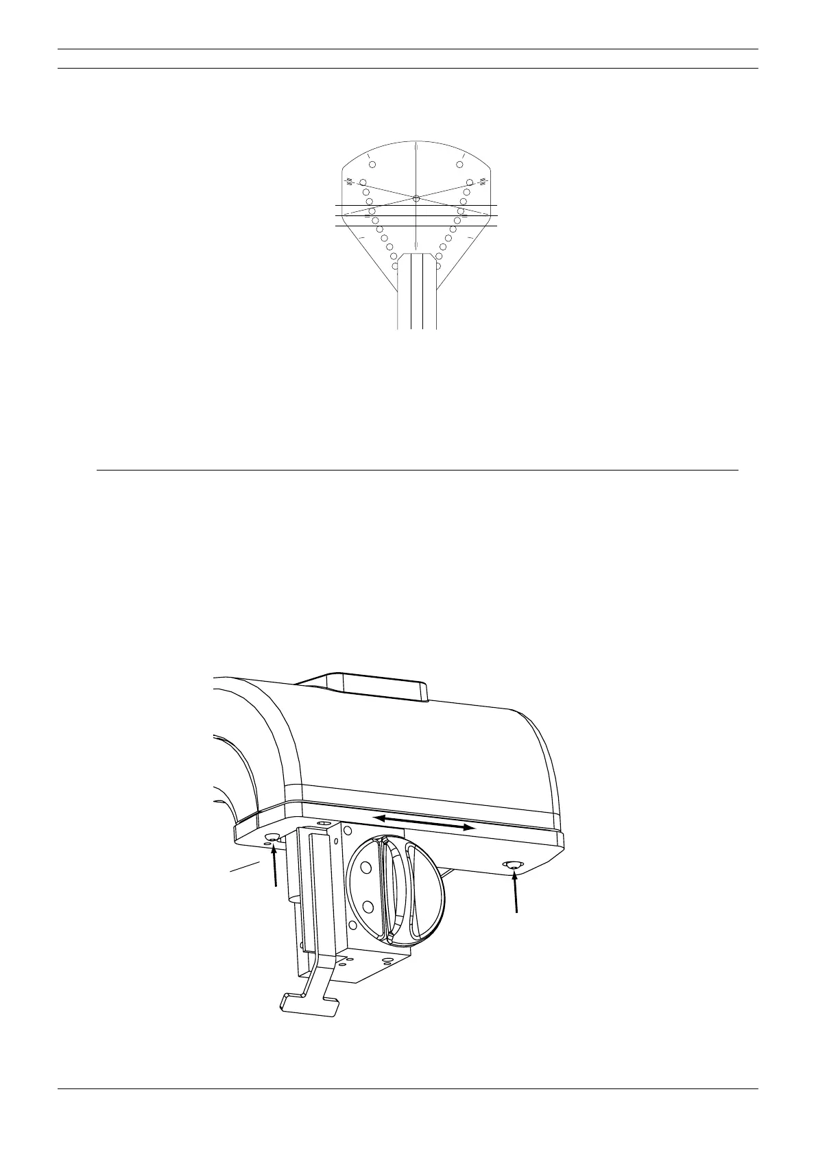
4.3 Adjusting the position of the sensor head
NOTE This section applies to panoramic units without cephalostat and pan/ceph units with one
sensor head (i.e. sensor head with quick connector mechanism). In case your x-ray unit is
a pan/ceph model with two fixed sensor heads, the position of the entire panoramic sen
-
sor head can not be adjusted. Refer to section “Adjusting the position of the optical sen-
sor of the sensor head” on page E-37 for instructions on adjusting the optical sensor
position.
The position of the sensor head can be slightly adjusted. Loosen the two screws that hold the
sensor head in rotating unit and move the sensor head to required position.
Figure 65
START
END
PLANMECA No.50971
X-LINE
Y-LINE
X-LINECA.EPS
Alignment ruler
Ball phantom
Tube head side
Sensor head side
D2_adjsenshead_1.eps
Loosen the screws.