Chapter E - DIMAX3 DIGITAL SYSTEM ADJUSTMENT
E-46 Planmeca Proline CC panoramic x-ray
Technical Manual
The sensor head is attached to its position in reverse order:
- Push the sensor head to its adapter.
- Place the lock disc to the adapter and tighten the attachment screw with the 3mm allen key.
- Push the button axle towards the lock disk. Make sure that the head of the axle goes into the
hole on the lock disc and tighten the attachment screw with 3mm allen key.
- To remove the sensor head clearance tighten the four screws located on the lock disc slightly
with 2.5mm allen key.
- Attach the covers.
6.2 Checking the sensor head position
The sensor head must be perpendicular to the head support. Use a sprit level to check the sen-
sor head position, i.e. the sensor alignment tool position (see Fig. 81 on page E-47). In case it is
not perpendicular to the head support, the angle of the quick connector mechanism must be
adjusted.
In case the sensor head is attached to the cephalostat, remove the sensor head from the quick
connector mechanism (see instructions given in Planmeca Proline CC panoramic x-rays user’s
manual). Remove the covers according to the instructions given in section
“Cephalostat sensor
head with quick connector mechanism - removing the covers” on page E-41.
In case the cephalostat is equipped with fixed sensor head, remove the covers and the sensor
head according to the instructions given in section
“Removing and attaching the fixed sensor
head” on page E-42.
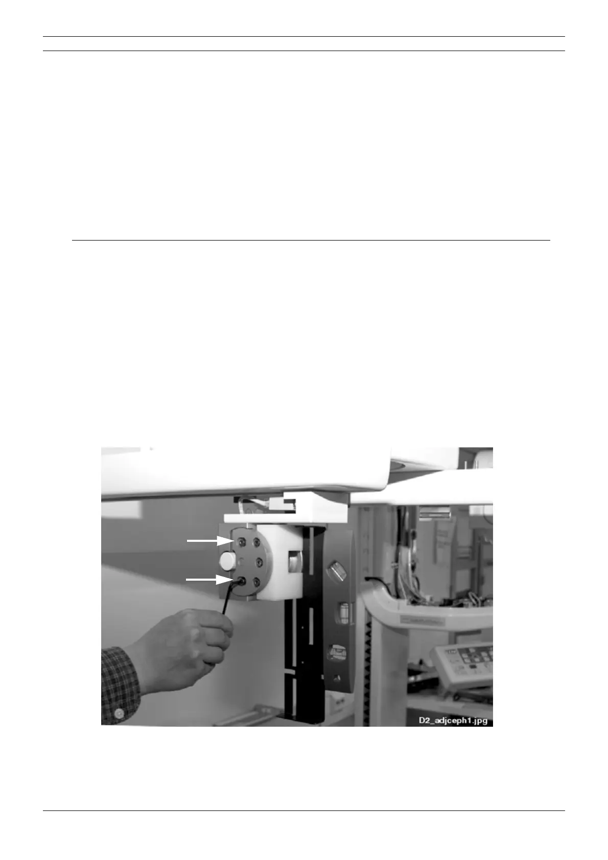
Attach the sensor alignment tool to the quick connector. Loosen the two screws located on the
outer side of the mechanism with the 3mm allen key.
Figure 80