Do you have a question about the Planmeca Proline CC and is the answer not in the manual?
Crucial safety warnings and precautions for servicing the unit.
Information regarding software revisions and manual validity.
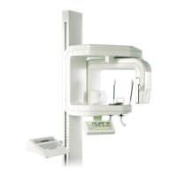
Detailed technical specifications of the X-ray unit.
Statement outlining usage and technical factors for the X-ray unit.
Overview of the unit's key features and protective mechanisms.
Description of the keyboard layout and key functions in normal and service modes.
Explanation of keyboard operations in the standard user mode.
Reference for standard keyboard operation and everyday use instructions.
Details on accessing and using special function modes and settings.
Functionality of the automatic return feature for cassette loading.
Procedure to disable the temple rest motor for unit usage.
How to switch the automatic temple support closing function on/off.
Enables X-ray operation without radiation for testing purposes.
Accessing and examining parameters of previous exposures.
Configuration of the Autoprint film marking system for orientation and date format.
Overview of functions and operations available in service mode.
Step-by-step instructions for entering and exiting the service mode.
Explanation of key meanings and display indicators specific to service mode.
Details on performing adjustments and calibrations within service mode.
How to view the total number of exposures taken by different counters.
Accessing and analyzing recorded error events for fault diagnosis.
Adjusting the slow speed for the up/down motor in both directions.
Selecting the type of remote exposure switch used with the unit.
Changing the unit's operating mode between panoramic and cephalostatic.
Entering the correct X-ray tube type into the system for proper operation.
Determining and setting the specific equipment model in service mode.
Restoring the unit to its default quick exposure settings.
List and explanations of help messages displayed on the main unit display.
A list of error codes and their corresponding explanations for troubleshooting.
Detailed explanations for various error codes encountered during operation.
Explanation of errors typically related to user actions or input.
Explanation of errors that are generally recoverable or transient.
Specific error related to the transversal slicing system functionality.
Explanation of errors occurring when operations exceed their time limits.
Explanation of errors related to the generator and its components.
Explanation of errors indicating mechanical faults or movement issues.
Explanation of errors associated with connector or cable issues.
Errors linked to the generator processor and Automatic Exposure Control.
Explanation of errors originating from software or communication issues.
Errors indicating problems with microprocessor chip functionality or memory.
Explanation of miscellaneous errors not categorized elsewhere.
List of specialized tools needed for calibration and adjustment procedures.
Procedures for aligning the X-ray beam in panoramic mode.
Steps to verify the alignment of the panoramic X-ray beam.
Calibrating the primary slot for correct beam positioning.
Steps to center the radiation beam if it's misaligned horizontally.
Procedures for checking and adjusting the patient positioning system.
Verifying the correct positioning and function of the patient positioning mechanism.
Detailed steps for adjusting the patient positioning mechanism.
Adjusting the mechanism's position perpendicular to the column.
Adjusting the mechanism's position fore/aft relative to the column.
Checking and adjusting the rotation movement's concentricity.
Procedures for checking and adjusting the patient positioning light beams.
Verifying the position and focus of the patient positioning lights.
Adjusting the light beams using mirror bracket manipulation.
Adjustments related to the mechanical components of the rotating unit.
Checking and adjusting the clearance of the guiding profile and counterprofile.
Adjusting the guidance wheel for optimal performance.
Setting and adjusting the start and end limits for the rotation movement.
Instructions for setting the unit's internal calendar clock.
Adjusting the volume and tone of the exposure warning signal.
Procedure for calibrating the Automatic Exposure Control system.
Adjusting primary slot positions for optimal AEC signal.
Adjusting the base mA value to achieve correct film density.
Fine-tuning the AEC signal values for accurate exposure control.
Procedures for adjusting and calibrating the cephalostat components.
Steps for removing the cover of the cephalostat cassette holder.
Verifying the correct positioning of the cephalostat head support.
Detailed instructions for adjusting the cephalostat head support.
Verifying soft tissue filter and its positioning light alignment.
Calibrating and adjusting the soft tissue filter positioning light.
Adjusting the soft tissue filter's position based on beam alignment.
Verifying the alignment of the X-ray beam for cephalometric exposures.
List of tools required for Dimax3 digital system setup and calibration.
Procedures for aligning the X-ray beam for the Dimax3 digital system.
Steps for removing and attaching the fixed sensor head.
Procedures for removing covers from the sensor head with quick connector.
Verifying the panoramic X-ray beam position with the Dimax3 system.
Adjusting the X-ray beam for optimal alignment with the sensor.
Correcting primary slot alignment for vertical beam issues.
Correcting primary slot alignment for horizontal beam issues.
Calibration process for the panoramic sensor head.
Procedures for checking and adjusting patient positioning for Dimax3.
Verifying the correct positioning of the patient positioning mechanism.
Detailed steps for adjusting the patient positioning mechanism.
Adjusting the mechanism's position perpendicular to the column.
Adjusting the mechanism's position fore/aft relative to the column.
Slightly adjusting the sensor head's position for optimal alignment.
Adjusting the optical sensor within the sensor head assembly.
Additional panoramic mode adjustments referencing other sections.
Procedures for adjusting and calibrating the cephalostat for Dimax3.
Initial steps before performing cephalostat adjustments.
Procedure for removing the second primary slot from the cephalostat.
Removing covers from the cephalostat sensor head assembly.
Steps for removing and attaching the fixed sensor head on cephalostat.
Verifying the sensor head's perpendicularity to the head support.
Aligning the X-ray beam for cephalometric exposures with Dimax3.
Adjusting the cephalostat arm for correct beam alignment.
Calibration process for the cephalostat sensor head.
Adjusting the image area position for patient's nasal side.
Adjusting the flat spring that fastens the frame cover.
Shifting the image area forwards or backwards for patient's nasal side.
General guidelines for maintaining the X-ray unit's systems.
Instructions for cleaning the unit's surfaces and components safely.
Routine checks to be performed by the operator for proper function.
Periodic checks to ensure optimal and accurate operation.
Verifying electrical parameters for maintaining initial accuracy.
Using service mode signals for tracing sensor and switch issues.
Reference to error messages and their explanations for fault finding.
Identification and function of all fuses within the equipment.
Troubleshooting steps for when the equipment fails to power on.
Verifying the mains outlet voltage is within acceptable operational limits.
Issues and recovery procedures when the backup battery is flat.
Diagnosing and resolving issues with the rotation mechanism.
Troubleshooting steps when the rotation part is immobile.
Diagnosing why the rotation mechanism stops mid-cycle.
Identifying causes for the rotation cycle becoming stuck.
Troubleshooting abnormal trembling during the rotation cycle.
Identifying sources of abnormal noise during the rotation process.
Resolving issues related to the cassette movement system.
Diagnosing why the cassette carriage fails to move.
Troubleshooting sudden stops of the cassette carriage.
Addressing trembling issues during cassette movement.
Identifying sources of abnormal noise in the cassette mechanism.
Resolving problems with the primary slot mechanism.
Troubleshooting steps when the primary slot fails to move.
Diagnosing incorrect stopping positions of the primary slot.
Resolving issues with focal trough movement adjustments.
Troubleshooting when forwards/backwards movement is non-functional.
Addressing abnormal movement areas in the focal trough mechanism.
Correcting incorrect position indications on the display.
Troubleshooting temple support mechanism issues.
Diagnosing why temple supports fail to move.
Resolving erroneous functioning of temple supports.
Troubleshooting Z-carriage up/down movement problems.
Diagnosing why the Z-carriage fails to move.
Addressing Z-carriage movement restricted to a single direction.
Troubleshooting steps for a stuck Z-carriage.
Resolving issues where the mechanism fails to respect movement limits.
Diagnosing common problems related to radiograph quality.
Identifying causes for general disturbances in radiograph quality.
Troubleshooting steps when no radiograph image is produced.
Diagnosing issues where exposure occurs but no image appears.
Addressing radiographs that appear too light.
Identifying causes for horizontal or vertical stripes on the film.
Resolving issues where the exposed area is improperly limited.
Procedures for removing and replacing various external covers of the unit.
Steps to remove the front and back covers of the tube head.
Procedure for removing the secondary slot cover.
Steps to remove the back cover of the cassette carriage.
Instructions for removing the rotating arm cover.
Steps for removing the lower shelf cover.
Procedures for removing the Z-carriage cover.
Instructions for removing the upper shelf cover.
Procedures for replacing the motors used in the unit.
Steps for removing and installing the Z-motor.
Procedures for replacing the rotating motor and gear assembly.
Steps for replacing the primary slot motor.
Procedures for replacing the cassette motor and gear.
Instructions for replacing the motors involved in positioning.
Procedures for replacing circuit boards in the unit.
Steps for removing and replacing the Low Power Supply PCB.
Procedures for replacing the Generator PCB.
Steps for removing and replacing the Generator Processor PCB.
Information on replacing the Keyboard Processor PCB and data backup.
Procedure for replacing the Keyboard PCB.
Steps for replacing the Layer Hold Limits circuit board.
Procedures for replacing the Primary Position Detector circuit board.
Detailed instructions for replacing the X-ray tube head assembly.
Overview of the unit's mechanical design and operational principles.
Description of the rotating mechanism's design and geometry.
Function and operation of the film cassette movement system.
Description of the tube head and its internal components.
Explanation of the collimator and primary slot mechanism's function.
Description of the patient positioning mechanism and its drive system.
Explanation of the Z-carriage height adjustment system.
Overview of the unit's electrical components and their functions.
Function of the tube head in converting power to X-rays.
Identification and functions of the nine circuit boards in the unit.
Description of the six motors and their operational methods.
Function and operation of the Z-carriage up/down motor.
Function and operation of the layer adjust motor for patient positioning.
Function and operation of the temple rest motor.
Function and operation of the motor driving the rotation part.
Function and operation of the motor driving the cassette carriage.
Function and operation of the motor controlling primary apertures.
Description of the three patient positioning lights.
Overview of the equipment's wiring concept and main cable routing.
Details on protective earthing connections for user safety.
Explanation of the electronic power supply voltages and tolerances.
Short description of signals in various interconnecting cables.
| Brand | Planmeca |
|---|---|
| Model | Proline CC |
| Category | Personal Care Products |
| Language | English |