Chapter E - DIMAX3 DIGITAL SYSTEM ADJUSTMENT
E-32 Planmeca Proline CC panoramic x-ray
Technical Manual
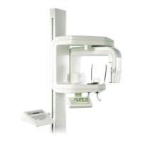
Leave the ball phantom tool in position and place alignment tool adapter to the sensor head.
Place one end of the alignment ruler in the first primary slot (the largest one) and the other end to
the sensor alignment tool.
Figure 57
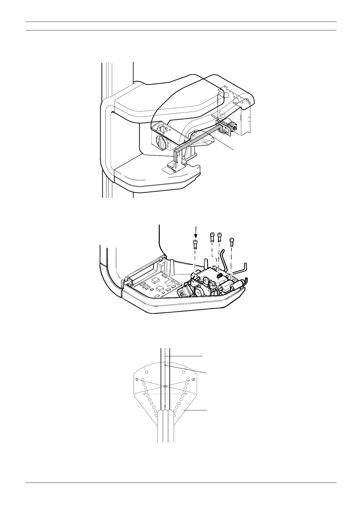
Loosen the four screws that hold the patient position mechanism in place and adjust its position
to the left or right until the mechanism is centered.
Figure 58
Make sure that the y-line on the ball phantom is parallel to the line on the underside of the align-
ment ruler. Note that the line on the ball phantom and the line on the alignment ruler do not have
to coincide, but they must be parallel, the deviation may be ±1mm.
Figure 59
Tighten the screws, and remove the alignment pin.
Take another ball phantom picture to check the alignment again. Readjust if necessary.
START
END
PLANMECA No.50971
X-LINE
Y-LINE
Dimax2_adj1.eps
Alignment ruler
Screws
START
END
PLANMECA No.50971
X-LINE
Y-LINE
Y-lineca.EPS
Alignment ruler
Lines do not have to coincide
but they must be parallel
Ball phantom