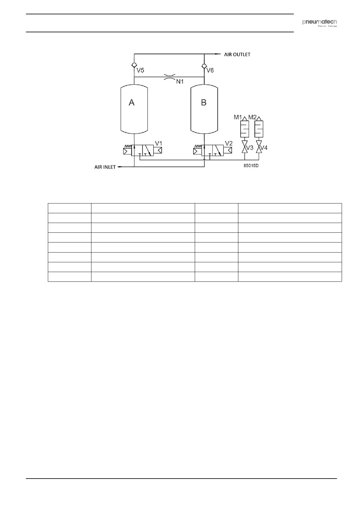
Flow diagram
Reference Designation Reference Designation
AIR INLET Air inlet V4 Regeneration valve
AIR OUTLET Air outlet V5 Left check valve
A Left desiccant tower V6 Right check valve
B Right desiccant tower M1 Blow off silencer
V1 Left 3–2 valve M2 Regeneration silencer
V2 Right 3–2 valve N1 Nozzle
V3 Blow off valve
Depending on dryer size, the dryer may consist of a single dryer module (see flow diagram) or a
combination of several dryer modules in parallel.
Operation principle
The operation cycle of the dryer is repetitive and is controlled by a factory set timer in the
controller or by the pressure dew point (PDP) sensor, which is optionally available. While the
desiccant in one tower dries the compressed air, the desiccant in the second tower is being
regenerated. Regeneration of the desiccant is achieved by means of purge air from the drying
tower.
The compressed air entering the dryer is led to one of the towers by means of one of the two 3–2
valves. The position of the 3–2 valves is controlled by the solenoid valves. As the air flows
upwards through the tower, the desiccant adsorbs the water vapor and the compressed air is
dried. The dried air leaves the dryer via the outlet check valve.
A small portion of the dried air passes a nozzle, expands to atmospheric pressure and flows
downwards through the other tower, regenerating (drying) the desiccant. A nozzle for operation of
the dryer at 7 bar is installed as standard. Alternative nozzles for use at different operating
pressures may be delivered with the units. Contact your supplier. The regeneration air is released
via the corresponding solenoid valve and the silencer. The solenoid valves are controlled by the
timer.
Instruction book
2920 7111 23 13