10.28
Battery and Electrical Systems
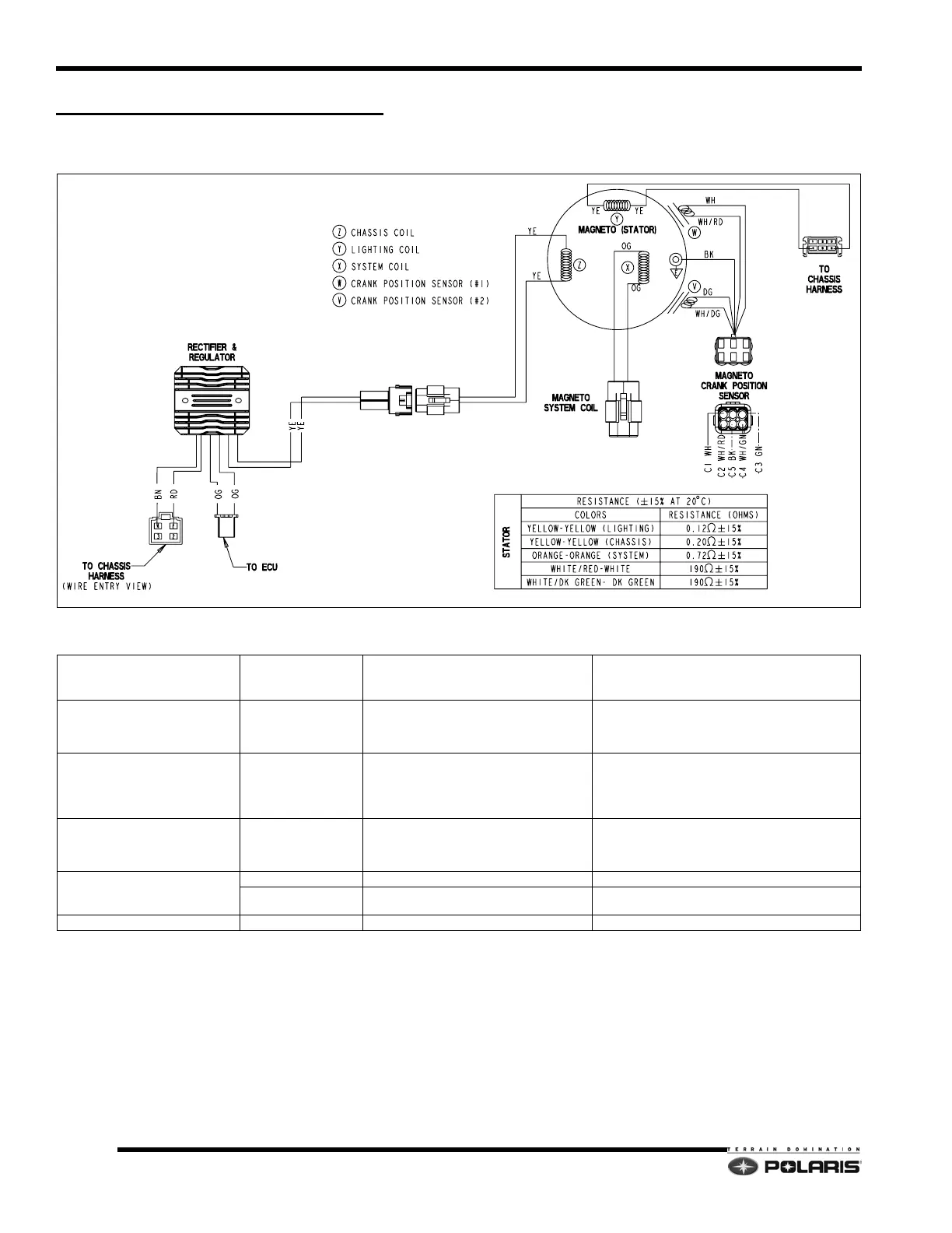
DC-CFI ELECTRICAL SYSTEMS
DC-CFI Stator Assembly
DC-CFI Stator Specifications
ITEM COLOR SYSTEM FUNCTION
RESISTANCE
+/- 15% @68
°F (20°C)
AC Lighting Coil (Y) YELLOW to YELLOW
14VAC Chassis Power
- Battery Charge (Electric Start Equipped)
- Head / Tail Lights
- Hand / Thumb Warmers
YELLOW TO YELLOW = 0.12
NO CONTINUITY TO GROUND
DC Chassis Coil (Z) YELLOW to YELLOW
14VDC Chassis Power
- Fuel Pump
- Chassis Relay Coil
- EV Solenoid
- Instrument Cluster
YELLOW TO YELLOW = 0.20
NO CONTINUITY TO GROUND
DC System Coil (X) ORANGE to ORANGE
16 VDC System Power
- Fuel Injector Power
- ECU / Sensor Power (Regulated to 5VDC)
- Ignition Coil Power
ORANGE TO ORANGE = 0.72
NO CONTINUITY TO GROUND
CRANK POSITION SENSOR (CPS)
GRN to WHT/GRN Crank Position Sensor (5 Tooth) Ignition timing GRN to WHT/GRN = 190
WHT to WHT/RED
Crank Position Sensor (2 Tooth)
Locates TDC and RPM
WHT to WHT/RED = 190
ENGINE GROUND BROWN Engine Ground 0
 Loading...