What to do if my Polaris Snowmobiles spark plugs are damaged?
- AAndrew LambertAug 19, 2025
If you find that the spark plugs are either fouled or damaged, you should replace them.
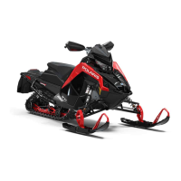
What to do if my Polaris Snowmobiles spark plugs are damaged?
If you find that the spark plugs are either fouled or damaged, you should replace them.
Why Polaris 850 MATRYX INDY XC 129 2021 Snowmobiles won't start because of ignition switch?
Make sure the key is in the ON / RUN position. You can also test the switch using continuity test tables in the Electrical Chapter.
Why Polaris 850 MATRYX INDY XC 129 2021 won't start because of auxiliary shut off switch?
Check that the auxiliary shut off switch is pulled up. You can also test the switch using continuity test tables in the Electrical Chapter.
How to test spark plug function on Polaris 850 MATRYX INDY XC 129 2021?
Use a commercially available spark plug tester set at the specified electrode gap.
How to inspect stator on Polaris Snowmobiles?
Test the stator coil resistance, referencing the Electrical Chapter for resistance specifications. Also, inspect the 2 and 5 tooth position sensors.
What type of spark plug do I need for Polaris 850 MATRYX INDY XC 129 2021 Snowmobiles?
Verify the specified spark plugs are installed and gapped to specification. Use NGK BPR9ES spark plugs with a gap of .27 in (.70 mm).
How to check fuel quality in Polaris 850 MATRYX INDY XC 129 2021 Snowmobiles?
To check the fuel quality in your snowmobile, inspect the fuel in the fuel tank. Use a commercially available fuel tester to verify the ethanol content is 10% or less.
What to do if Polaris 850 MATRYX INDY XC 129 2021 Snowmobiles fuel pump is not getting power?
To troubleshoot fuel pump power issues: 1. Connect a fully-charged 12V battery to the fuel pump prime connector. The fuel pump should turn on. 2. Connect Digital Wrench to the vehicle. 3. Use Output state control to test the fuel pump function. The ECU must command the fuel pump to turn on when using Output State Control testing.
What to do if my Polaris Snowmobiles is low on fuel?
Refill the fuel tank with fresh fuel. Note that the fuel pump may require priming or the fuel system may need to be purged of air if the snowmobile has run out of fuel.
How to check cylinder compression on Polaris Snowmobiles?
Test both cylinders under the same conditions using the same compression tester. Ensure the compression difference between the cylinders is 15% or less.
| Engine | 850 Patriot |
|---|---|
| Engine Type | 2-Stroke |
| Cooling System | Liquid |
| Fuel System | Electronic Fuel Injection (EFI) |
| Horsepower | 165 hp |
| Track Length | 129 in |
| Track Width | 15 in |
| Ski Stance | 42 in |
| Brake | Hydraulic Disc |
| Electric Start | Yes |
| Reverse | Yes |
| Bore x Stroke | 85 mm |
| Track Height | 1.25 in |
| Fuel Capacity | 11.5 gal |
| Front Suspension Type | Independent |
| Front Shocks | Walker Evans Needle Shocks |
| Rear Shocks | Walker Evans Needle Shocks |
Details on model number designation, VIN, and tunnel decal.
Information on replacement keys and publication part numbers.
Lists special tools required for servicing and their supplier.
Details on model numbers and corresponding images.
Clutch settings for various models based on altitude.
Provides master torque table for various components.
Table for converting units of measure.
Lists SAE tap and drill sizes.
Lists metric tap and drill sizes.
Table of decimal equivalents for fractions.
Recommendations for fuel types for North America and International markets.
General safety precautions and important notes for service work.
Covers diagnostic trouble codes (DTCs) for the MATRYX system.
Detailed list of diagnostic trouble codes, SPN, FMI, P-Code, and condition.
Overview of Digital Wrench software capabilities and special tools.
Information on configuring the Digital Wrench software.
Explains how to display DTCs and interpret the information.
Describes how to view real-time vehicle data.
Explains how to use the Meters button to display data.
Explains how to use the Data Trigger function for freeze frame recording.
Overview of the Special Tests Menu and its functions.
Explains how to access vehicle historical information.
Describes how to perform output state control tests.
Details on generating and submitting service reports.
Menu for ECU, injector, and oil pump replacement procedures.
Overview of the ECU reprogramming (reflash) process.
How to verify ECU and instrument cluster information using Digital Wrench.
Information on the PMDW app for Android devices.
Diagnostic procedures for the PVT system.
Troubleshooting causes and solutions for belt wear and burning.
Analysis of steering and suspension components for wear and damage.
Analysis of shock oil misting or leakage.
General notes and procedures for diagnosing electrical problems.
Methods for testing DC circuits, including static and dynamic tests.
Guidelines for front probing, back probing, and break out testing.
Procedure for testing continuity and resistance in electrical circuits.
Procedure for testing for shorts to ground in electrical circuits.
Procedure for testing for shorts to voltage in electrical circuits.
Diagnosing intermittent electrical failures related to poor connections.
Procedure for performing a current flow test.
Procedure for testing parasitic draw when the key is off.
Procedure for testing voltage drop in a circuit.
General information on maintaining emission control devices and systems.
Information on emission control devices and systems.
Details on the factory-installed emissions information label.
Requirements for operating on gasoline and engine tune-ups.
Information for individuals with implantable medical devices.
Details on the L-wrench and spare belt container.
Procedures for engine, drive belt, and track break-in.
Guidelines for initial engine break-in.
Recommended maintenance schedule and service checks.
Items to be inspected before each ride.
Maintenance tasks to perform before the season.
Chart outlining required maintenance based on vehicle miles.
List of products including oils, antifreeze, greases, and cleaners.
Procedures for removing and installing hood and side panels.
Maintenance procedures for the engine.
Procedure to inspect throttle lever freeplay.
Procedure to adjust throttle lever freeplay.
Procedures for inspecting and replacing spark plugs.
Inspection of spark plug wires and caps.
Maintenance procedures for the cooling system.
Procedure to check the coolant level in the reservoir.
Procedure for bleeding the cooling system.
Maintenance procedures for the drive belt and clutches.
Procedure for removing the drive belt.
Procedure for installing the drive belt.
Inspection and adjustment of belt-to-sheave clearance.
Procedure for inspecting clutch alignment and offset.
Procedure for adjusting clutch offset and float.
Procedure for cleaning clutch sheaves.
Maintenance procedures for fuel, air intake, and exhaust systems.
Maintenance procedures for the fuel system.
Information on intake screens and their maintenance.
Inspection of the exhaust system components.
Maintenance procedures for the drive system.
Procedure to adjust drive chain tension.
Procedure to check the chaincase oil level.
Procedures for changing chaincase oil.
Maintenance procedures for the brake system.
Inspection of brake system components.
Procedure to check and add brake fluid.
Procedure for bleeding the brake system.
Maintenance procedures for steering and suspension systems.
Service procedures for handlebar components.
Torque specifications for handlebar components.
Illustration showing handlebar component locations.
Procedure for adjusting handlebar angle.
Procedure for adjusting handlebar riser angle.
Procedure for adjusting the left hand control.
Service procedures for the front suspension.
Inspection of front suspension components.
Procedures for inspecting and adjusting ski alignment and toe.
Inspection and replacement of ski skags.
Service procedures for the rear suspension.
Procedure for inspecting rail sliders.
Procedure for inspecting the track for damage.
Procedure for aligning the track.
Procedure to inspect track tension.
Procedure to adjust track tension.
Maintenance procedures for the electrical system.
Maintenance procedures for the battery.
General battery maintenance guidelines.
Procedure for removing the battery.
Procedure for installing the battery.
Procedure for activating the battery.
Information on using the battery tender port.
Procedures for storing the battery during off-season.
General information and service specifications for the engine.
Notes regarding oil pump enrichment mode timer resets and priming.
List of special tools required for engine service.
Information on electronic oil pump mounting and flow offset identification.
Assembly view and service procedures for the oil tank.
Procedures for engine removal and installation.
General information and specifications for 650 and 850 engines.
Torque sequences for engine component assembly.
Illustrations showing proper orientation of components.
Procedure for applying crankcase sealant.
Assembly views of engine components.
Exploded view of cylinder assembly with part identification.
Procedures for stator and flywheel removal and inspection.
Inspection and service procedures for the reed valve assembly.
Inspection of reed petals for damage.
Procedure for removing reed petals.
Procedure for installing reed petals.
Procedures for engine disassembly and inspection of top end components.
Procedure for removing the cylinder head.
Procedure for inspecting the cylinder head for flatness.
Procedure for removing the cylinder.
Procedure for inspecting cylinder walls for wear.
Procedure for honing the cylinder bore.
Procedure for removing the piston.
Information on piston markings indicating official measurement locations.
Procedure for inspecting the piston for scoring or cracks.
Information on piston ring directional installation.
Procedure for measuring and checking piston ring installed gap.
Inspection and replacement procedures for the piston needle bearing.
Procedures for engine disassembly and inspection of bottom end components.
Procedure for disassembling the crankcase.
Procedure for removing the crankshaft.
Inspection of the lower crankcase cross shaft gallery.
Inspection of lower connecting rod bearings.
Inspection of main bearings on the crankshaft.
Inspection of the PTO bearing.
Overview of diagnostic power connector functions.
Connects diagnostic power to Next-Gen Service Power Harness.
Details on engine hot LED and ECU shutdown modes.
Troubleshooting steps for engine overheating.
Explains DET protection modes and instrument cluster indicators.
Troubleshooting steps for DET activation.
Explains the engine shutdown feature for extended idle.
Overview of the Cleanfire Fuel Injection system components and functions.
Information on the EGT sensor, its location, and testing.
Information on the T-MAP sensor and its testing.
Details on the two crankshaft position sensors and their functions.
Procedure for inspecting and adjusting CPS air gaps.
Information on ignition coil packs and resistance specifications.
Information on the ECT sensor, its location, and resistance values.
Information on the knock sensor, its location, and torque.
Information on the fuel pressure sensor and testing procedures.
Details on ECU connectors and labels.
Pinout diagram for the ECU (CNA) 34-pin connector.
Pinout diagram for the ECU (CNB) 34-pin connector.
Information on the ECU label and its importance.
Location and mounting instructions for the ECU.
Overview and testing procedures for the TPS.
Information on routing the TPS wire lead.
Overview, operation, and troubleshooting of the PERC system.
General warnings and information for servicing the fuel system.
Important safety warnings for fuel system service.
Recommendations for fuel types in North America and International markets.
Recommendations for using fuel system deicers.
Procedure for priming the fuel pump.
Procedure for priming fuel pump without a service tool.
Procedure to change fuel type designation on the standard gauge.
Procedure to change fuel type designation on the 7S display.
Assembly views and service procedures for injectors, fuel rail, and throttle body.
Exploded view of the fuel rail and throttle body assembly.
Procedure for disconnecting and reconnecting fuel hose fittings.
Procedure for removing the throttle body.
Procedure for installing the throttle body.
Procedure for removing the fuel rail and fuel injectors.
Procedure for reinstalling fuel injectors and fuel rail.
Information on fuel injectors, including part numbers and position.
Service procedures for fuel injectors.
Service procedures for the fuel tank.
Exploded view of the fuel tank assembly.
Procedure for removing the fuel tank.
Procedure for installing the fuel tank.
Service procedures for the fuel pump.
Specifications for the fuel pump wire harness and pressure.
Procedure for removing the fuel pump.
Procedure for installing the fuel pump assembly.
Routing instructions for the fuel pump wire harness.
Service procedures for fuel lines.
Routing instructions for supply and return fuel lines.
Securing the fuel supply and return lines with a panduit.
Information on drive gears, drive chains, and chaincase sprocket ratios.
Part numbers and descriptions for drive gears.
Part numbers and descriptions for drive chains.
Chart of sprocket combinations and theoretical vehicle speeds.
Stock chaincase gearing settings for 650 models.
Stock chaincase gearing settings for 850 models.
Procedure to recalibrate speedometer offset after gearing changes.
Service procedures for the chaincase.
Exploded view of the chaincase assembly.
Procedure to adjust drive chain tension.
Procedure to check chaincase oil level.
Procedures for changing chaincase oil.
Verification of correct gasket installation in the cover groove.
Service procedures for the driveshaft.
Exploded view of the driveshaft assembly.
Procedure for removing the driveshaft.
Procedure for installing the driveshaft.
Service procedures for the jackshaft.
Exploded view of the jackshaft assembly.
Procedure for removing the jackshaft.
Procedure for installing the jackshaft.
General notes and procedures for the brake system.
Important points to consider when bleeding hydraulic brakes.
Exploded view of the brake system assembly.
Exploded view of the master cylinder assembly.
Inspection of brake lever travel and feel.
Procedure to check and add brake fluid to the reservoir.
Procedure for bleeding the brake system.
Inspection and replacement of phantom brake pads.
Service procedures for the brake lever and master cylinder.
Procedure for replacing caliper piston and seals.
Inspection and replacement of the brake disc.
Routing instructions for the brake line.
Guidelines for track studding and lug height.
Information on track studding recommendations.
Details on stud protection kits for the Matryx chassis.
General information on PVT system components.
List of special tools for the PVT system.
Information on drive spring function and effect on RPM.
Information on clutch weight function and effect on RPM.
Definition of neutral speed in the PVT system.
Definition of engine engagement RPM.
Definition of shift out over-rev.
Information on shift out RPM during WOT operation.
Information on driven spring function and effect on acceleration.
Explanation of back-shifting in the drive system.
Importance of final drive gear ratio for overall drive system performance.
Specifications and inspection procedures for the drive belt.
Specifications for drive belts, including dimensions and notes.
Procedures for inspecting the drive belt for wear.
Procedure for removing the drive belt.
Procedure for installing the drive belt.
Procedures related to the drive clutch.
Information on identifying the drive clutch part number.
Exploded view of the drive clutch assembly with part numbers.
Procedure for removing the drive clutch.
Procedure for disassembling the drive clutch.
Procedure for removing rollers, bushings, and roller pins.
Procedure for installing rollers, bushings, and roller pins.
Procedure for installing spider buttons.
Procedures for replacing clutch bushings and inserts.
Procedures for removing and installing moveable sheave bushings.
Procedures for removing and installing cover bushings.
Procedure for assembling the drive clutch.
Procedure for adjusting belt-to-sheave clearance.
Procedure for indexing the spider for clutch balance.
Procedures related to the driven clutch.
Exploded view of the Team LWT driven clutch assembly.
Procedure for removing the driven clutch.
Procedure for disassembling the driven clutch.
Procedure for assembling the driven clutch.
Procedure for installing the driven clutch.
Adjustments for the PVT system.
Procedure for inspecting clutch alignment and offset.
Procedure for adjusting clutch offset and float.
Procedure for cleaning clutch sheaves.
General information on steering and suspension systems.
Inspecting steering and suspension components for wear or damage.
Procedure for aligning rod ends in suspension assemblies.
Ensuring proper rod end engagement.
Specifications for front suspension width, toe, and camber.
Assembly views of steering and front suspension components.
Exploded view of the upper steering and handlebar assembly.
Exploded view of the hand guard assembly.
Exploded view of the lower steering assembly.
Exploded view of the front suspension assembly.
Exploded view of front shock mounting for XC models.
Exploded view of front shock mounting for VR1 models.
Exploded view of front shock mounting for Switchback Assault 146.
Exploded view of the ski assembly.
Exploded view of the front sway bar assembly.
Service procedures for steering and front suspension.
Procedures for steering post removal and installation.
Service procedures for the ski.
Procedure for removing the ski.
Procedure for installing the ski.
Service procedures for the spindle.
Procedure for removing the spindle.
Procedure for installing the spindle.
Service procedures for control arms.
Procedure for removing the lower control arm.
Procedure for installing the lower control arm.
Procedure for removing the upper control arm.
Procedure for installing the upper control arm.
Service procedures for control arm pivots.
Procedure for replacing spherical bearings.
Exploded views of PRO-CC rear suspension assemblies.
Exploded views of IGX 146 rear suspension assemblies.
Service procedures for PRO-CC model shocks.
Procedures for front track shock (FTS) service.
Procedures for rear track shock (RTS) service.
Procedures for IGX 146 model shocks.
Procedures for front track shock (FTS) service.
Procedures for PRO-CC rear suspension removal and installation.
Procedure for removing the PRO-CC rear suspension.
Procedure for installing the PRO-CC rear suspension.
Information on normal side-to-side play in the rear suspension.
Procedures for IGX 146 rear suspension removal and installation.
General setup and adjustments for all models.
Procedures for handlebar components.
Torque specifications for handlebar components.
Illustration showing handlebar component locations.
Procedure for adjusting handlebar angle.
Procedure for adjusting handlebar riser angle.
Procedure for adjusting the left hand control.
Procedure for removing the two-piece throttle control.
Procedure for installing the two-piece throttle control.
Procedures for front suspension adjustments.
Procedure for adjusting control arm pivots.
Procedures for inspecting and adjusting ski alignment and toe.
Inspection and replacement of ski skags.
General cautions and notes for working with bonded components.
Important safety precautions and notes for chassis service.
Exploded views of chassis components.
Exploded view of the right bulkhead and chaincase assembly.
Exploded view of the left bulkhead and side support assembly.
Exploded view of the over structure assembly.
Exploded view of the clutch guard and footrests assembly.
Exploded view of the tunnel assembly.
Exploded views of body components.
Exploded view of the hood assembly.
Exploded view of the hood foam assembly.
Exploded view of the hood cap assembly.
Exploded view of the nosepan assembly.
Exploded view of the right fender assembly.
Exploded view of the left fender assembly.
Exploded view of the right side panel assembly.
Exploded view of the left side panel assembly.
Exploded view of the console assembly.
Exploded view of the seat assembly.
Assembly views of the bumpers.
Exploded view of the front bumper assembly.
Exploded view of the rear bumper and closeoff assembly.
Service procedures for body panels.
Procedure for removing the side panel.
Procedure for installing the side panel.
Procedure for removing the hood.
Procedure for installing the hood.
Procedure for removing the console.
Procedure for installing the console.
Information and procedures for bonded components.
Illustrations showing adhesive application patterns.
Procedure for removing the bulkhead floor plate.
Procedure for installing the bulkhead floor plate.
Procedure for removing the front tunnel bulkhead cooler.
Procedure for installing the front tunnel bulkhead cooler.
Procedure for removing the left bulkhead clip.
Procedure for installing the left bulkhead clip.
Procedure for removing the right bulkhead clip.
Procedure for installing the right bulkhead clip.
Procedure for removing the left support brace.
Procedure for installing the left support brace.
General information and electrical system cautions.
General safety cautions for the electrical system.
Specifications for spark plugs and ignition timing.
Information on charging and lighting systems.
Specifications for ignition timing.
Information on connecting the diagnostic power connector.
Information on electrical harnesses.
Locations of chassis harness components.
Locations for retaining chassis harness components.
Routing instructions for the chassis harness.
Locations of rear harness components.
Routing and retention instructions for the rear harness.
Locations of hood harness components for standard cluster.
Routing and retention for hood harness (standard cluster).
Locations of hood harness components for 7S display.
Routing and retention for hood harness (7S display).
Information on handlebar harness components.
Locations of handlebar harness components.
Routing and retention for handlebar harness.
Pinout information for handlebar connectors.
Procedure for inspecting handlebar harness connector terminals.
Procedure for de-pinning handlebar harness connector terminals.
Overview of the left hand control features.
Pinout diagram for the left hand control.
Diagnostic trouble codes for the left hand control.
Service procedures for the left hand control.
Routing instructions for additional sensors and components.
Routing instructions for the EGT sensor.
Routing instructions for the speed sensor harness.
Routing instructions for the knock sensor harness.
Routing instructions for the ECT sensor harness.
Routing instructions for the ignition coil harness.
Routing instructions for the fuel injector harness.
Routing instructions for the oil pump jumper harness.
Details and location of the load center.
Details on load center circuits, pins, and functions.
Details on relays and fuses within the load center.
Location of the load center.
Battery specifications and service procedures.
Procedure for installing the battery.
Information on identifying battery types.
Procedure for activating dry-shipped AGM batteries.
Information on low maintenance batteries.
Procedures for charging AGM batteries.
Procedures for testing AGM batteries.
Methods for testing battery performance.
Information on using a conductance analyzer for battery testing.
Procedure for testing battery open circuit voltage.
Procedure for performing a battery load test.
Procedure for measuring electrolyte strength or specific gravity.
Procedures for standard instrument cluster.
Overview and procedures for the 7S display.
Information on LED headlights and taillights.
Exploded view of the headlight assembly.
Overview of LED headlight components.
Procedure for removing the LED headlight.
Procedure for installing the LED headlight.
Exploded view of the taillight assembly.
Overview and service information for LED taillights.
Overview, location, and details of the PBR.
Description of the PBR as a power distribution device.
Location of the PBR on the vehicle.
Details of PBR connectors and their functions.
Diagram of the PBR circuit.
Information on testing the PBR.
List of PBR diagnostic trouble codes and their causes/actions.
Procedure for updating or replacing the PBR.
Information on the stator circuit and architecture.
Diagram of the stator circuit and architecture.
Tests to determine the condition of the stator.
Routing instructions for the stator harness.
Information on the ferrite suppressor and its function.
Information on controllers and converters.
Details on the EV actuator wire harness connector.
Pinout diagram for the EV actuator connector.
Routing instructions for the EV actuator wire harness.
Information on various switches.
Procedure for testing the ignition switch.
Procedure for testing the oil level sender.
Procedure for testing the auxiliary stop switch.
Information and testing for the throttle release switch.
Information on the brake switch.
Information on the optional tether switch.
Information on fuses, diodes, and resistors.
Information on the circuit breaker.
Information on relays.
Overview of relays.
Information on capacitors.
Overview of the ground speed sensor capacitor.
Procedure for measuring capacitance.
Information on the electric start and battery bracket.
Exploded view of the battery bracket assembly.
Routing instructions for the electric start harness.
Routing instructions for the battery harness.
Exploded view of the starter motor and flex drive assembly.
Procedure for removing the starter motor, flex drive, and pinion gear.
Procedure for installing the starter motor, flex drive, and pinion gear.
Procedure for bench testing the starter solenoid.
Information on accessing and viewing circuit diagrams.
Overview of the ignition control system and software stop.
Circuit diagram for the Next-Gen Service Power Harness.
Information on the SmartWarmers system.
Overview of the SmartWarmers system.
Procedure for calibrating heated grips.






 Loading...