76 MAN. PS 254 EN – Ind. 2
5. APPENDIX
5.1. Built-in programs
The Polysoude weld lab developed these
programs for mild steel and stainless steel
tubes. Starting from frequent applications they
represent the base to work out rapidly your
own weld programs. Please look for a program
close to your application in order to modify it.
Before you can use such a built-in program
you have to copy it in one of the 16 user
program places in the memory of the power
source (for detailed information, see
Programming Manual). Afterwards you can
modify the program to fit your special
application.
For all applications, Argon is used as shielding
gas. The programs are listed in function of the
welding head (closed chamber, MU III, or
TS/TP), the material (mild steel or stainless
steel), the diameter and the wall thickness of
the tubes to be welded. In case of tube to tube-
plate welds, a difference is made between
"flush" and "protruding" tubes.
Warning If multipass welding is
necessary, the parameter
values for the passes are
given in the tables without
repeating diameter and
thickness of the tubes.
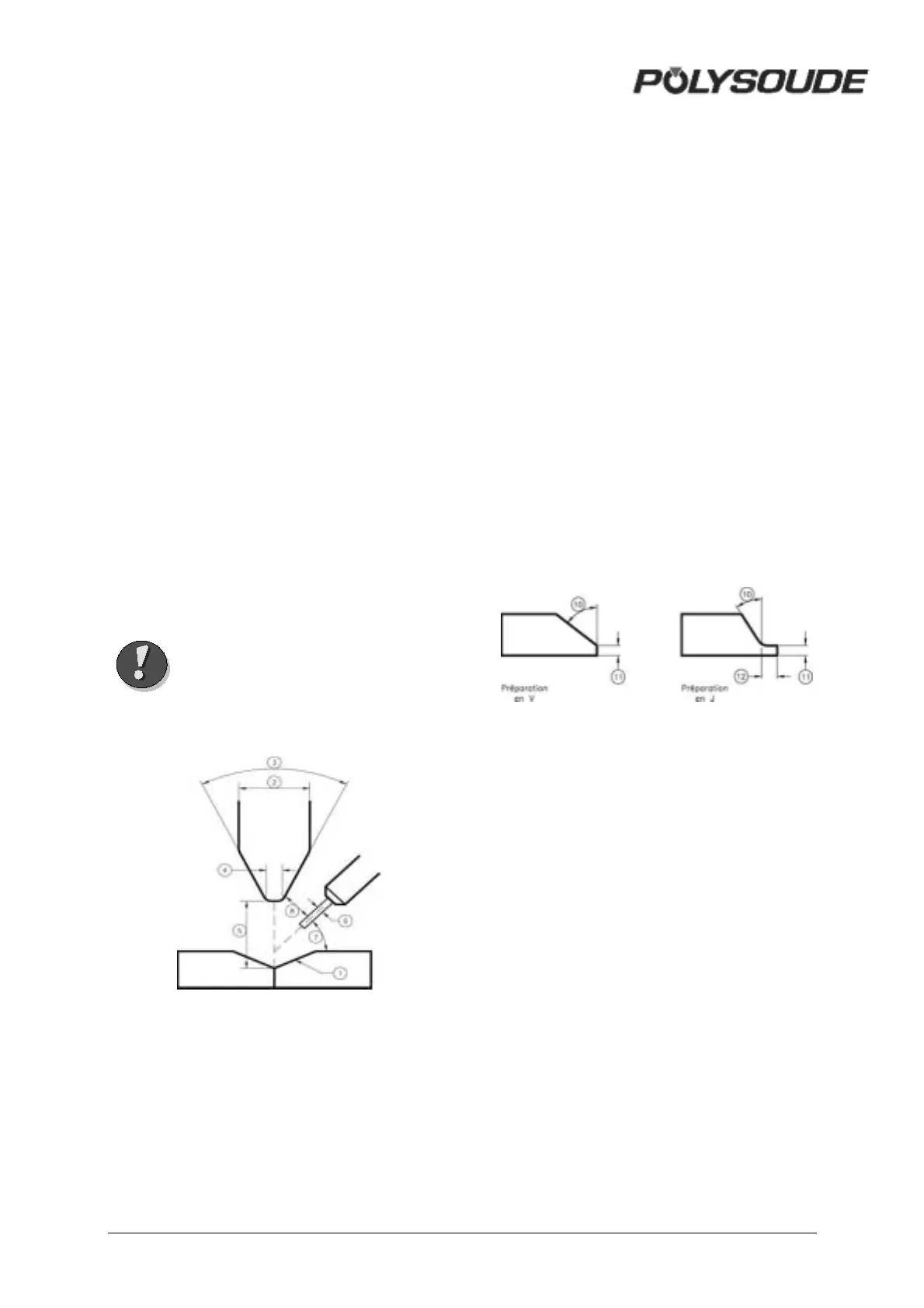
Fig. 5.1 : Weld set-up
If filler wire is used, its diameter is always 0.8
mm.
The set-up of a weld may influence
considerably its result. The set-up is explained
below and, whenever necessary, added to the
programs.
1: Tube end preparation.
2: Electrode diameter.
3: Tip angle.
4: Flat.
5: Distance electrode-workpiece.
6: Diameter of filler wire.
7: Angle between wire and workpiece.
8: Start position of the weld.
9: Start position of the weld.
10: Weld preparation angle.
11: Thickness of land.
12: Length of the land (for J
preparation).
Fig. 5.2 : Weld preparation