52 MAN. PS 254 EN – Ind. 2
3.4. Execution of a weld program
3.4.1. Safety precautions
Warning Before starting any
manipulation on the
equipment please refer to
chapter 1.2 "Safety
precautions".
3.4.2. Choosing the program to be
executed
The program to be executed is selected with
the switch BT 4 on the remote control pendant.
You can check the name of the program on the
display of the PS 254. If only "POLYSOUDE
PS 254" appears, you have selected the
number of a user program place where nothing
is stored in the memory of the PS 254. If !75! is
displayed on the screen, the right range of
current is not selected.
3.4.3. Simulation
After the correct program has been
selected, you can run a simulation without
affecting the workpiece to be welded. In
this case, all the functions of the selected
program are carried out except those
concerning the arc and the coolant circuit.
The gas controls are executed but the flow
rates are not considered. So it is possible to
check flow adjustment or reduce gas
consumption during the simulation.
The choice between a simulated or a real weld
cycle is made with the switch BT 1 on the
remote control pendant.
Fig. 3.6 : "Set up / weld" selector switch
3.4.4. Weld cycle
! Starting the weld cycle
The weld cycle is initiated by pressing the
button BT 5 on the remote control pendant.
The indicator BT 3 becomes illuminated when
the cycle starts. If for the selected number a
program does not exist in the memory of the
PS 254, no cycle will be started and the
indicator will flash. The flashing can be turned
off by pressing any button on the remote
control pendant.
Fig. 3.7 : "Start cycle" button
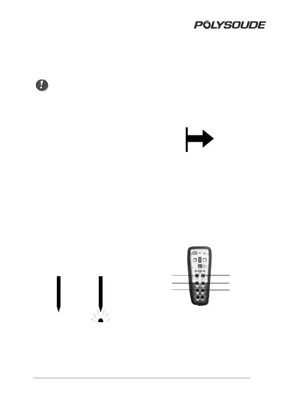
! Modification of a weld cycle
Parameter values can be modified during the
weld cycle with the remote control pendant.
The values of the modifiable parameters in
each sector are:
• The current or maximum current in the
case of pulsed current (I22).
• The rotation speed (V32) or low rotation
speed in case of pulsed rotation (V33).
• The wire speed or the high wire speed in
the case of pulsed wire (V42).
Fig. 3.8 : "Delta" buttons for
modifications of parameter values
BT 13
BT
8
BT 10
BT 14
BT 9
BT 11