3-9
3 First Steps
Back view
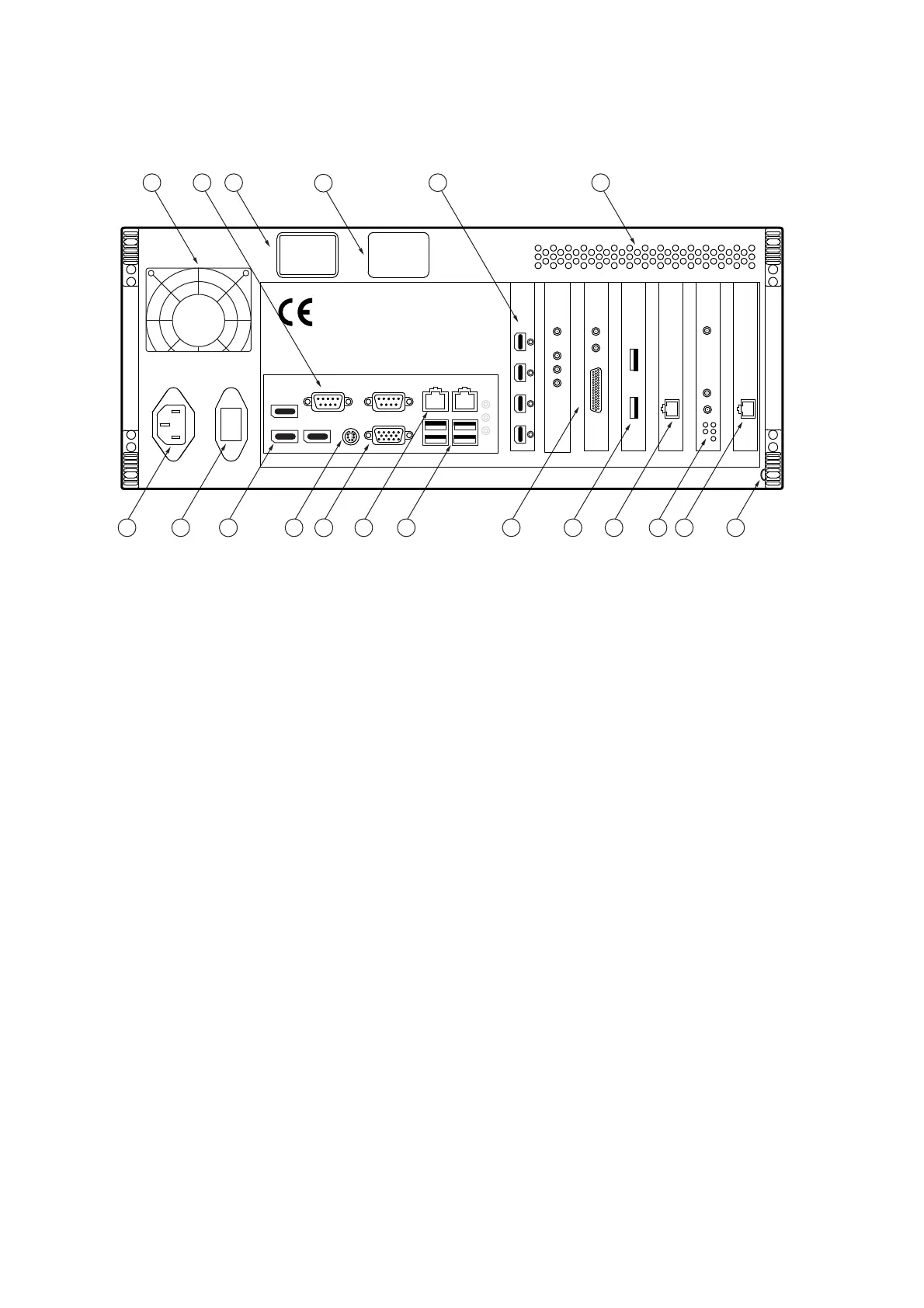
The back view of the industrial PC is shown in the following figure.
Figure 3.6: Back view of the industrial PC
1
Cooling fan
2
Serial interfaces (9-pin Sub-D plugs); not used
3
Name plate
4
Warning label
5
Monitor connections (Mini DisplayPort jacks)
6
Air vents
7
Connection for cable shielding (blade connector)
8 GENERATOR
network connection (only MSA-600-U; marked in red)
9 GENERATOR
connections of the generator board (only MSA-600-X)
10 CONTROL
network connection (marked in yellow)
11
USB connections (Universal Serial Bus, type A)
12 ACQUISITION
connections of the data acquisition board
13 VIDEO
network connection (marked in blue)
14
Monitor connection (VGA connection); not used
15
Connection for mouse/keyboard (PS/2 interface); not used
16
DisplayPort connections; not used
17 I/O
mains switch
18
Mains connection (socket for standard power cord)
,
2
&K
&ON,Q
7UJ
'3
'3
'3
$&48,6,7,21
*(1(5$725
9,'(2
0RQLWRU
&/.
75,*
6<1&
$
;
'3
%
*3,2
&21752/