3-24
3 First Steps
Sensor head
7. Feed the protective earth cable of the controller to the left connection for
the protective earth cable on the back of the sensor head.
8. Feed the protective earth cable of the objective positioner (with
MSA-A-TMS option) to the right connection for the protective earth cable
on the back of the sensor head.
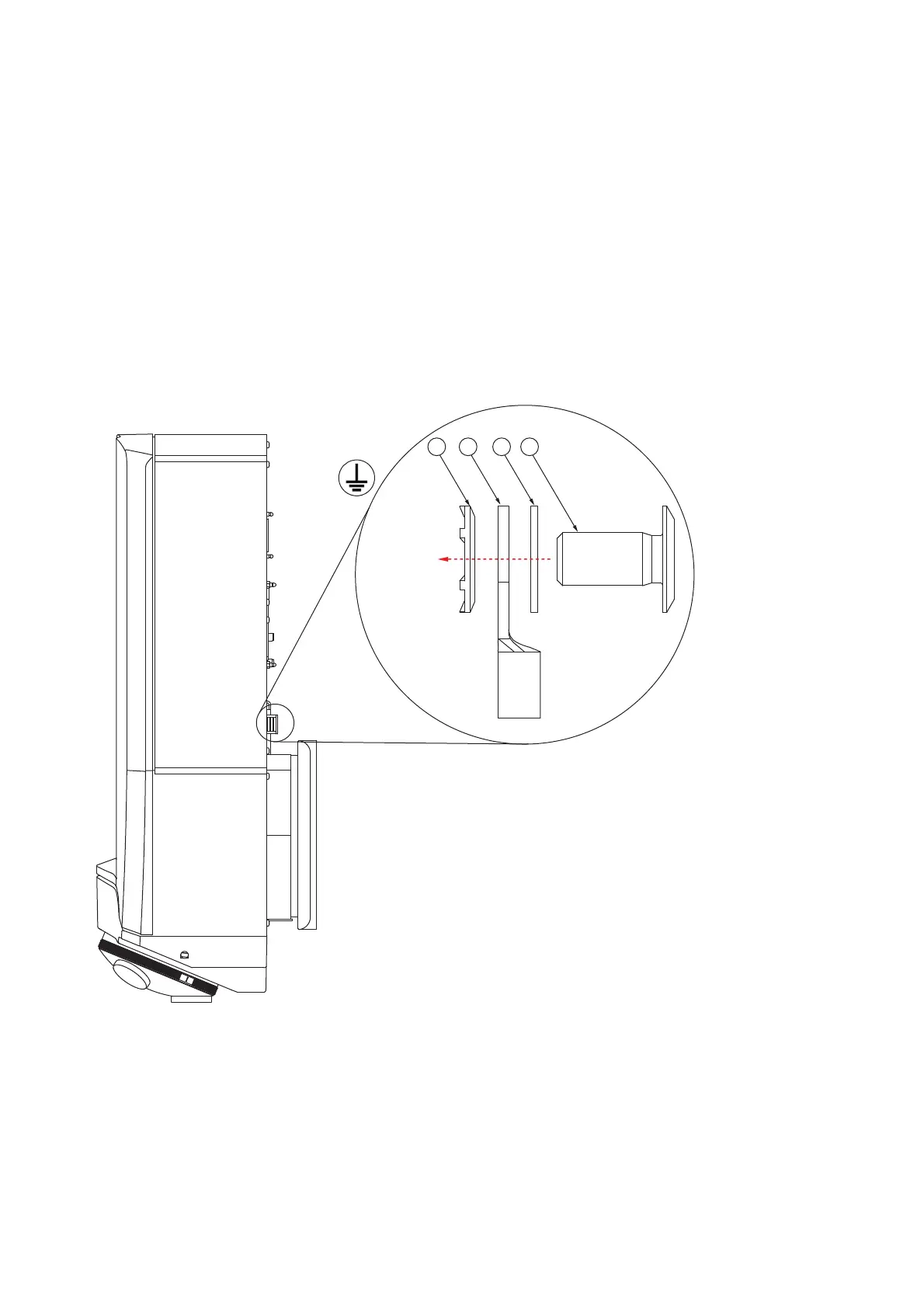
9. Connect the two protective earth cables as shown in F
IGURE
3.18. In doing
so, guide the protective earth cable of the controller upwards and the
protective earth cable of the objective positioner downwards, as this
protects the cables.
10. Tighten the screw [D] with a torque of 1.1 Nm.
11. Make sure that the contact resistance is < 0.1 Ω at 25 A at all connection
points relevant for mounting the protective earth cables.
Figure 3.18: Connection for the protective earth cable on the back of the sensor head
A
M4 contact washer
B
M4 cable lug
C
Washer Ø 4.3 mm for M4 screw
D
M4 x 8 head screw (special screw with a very flat head)