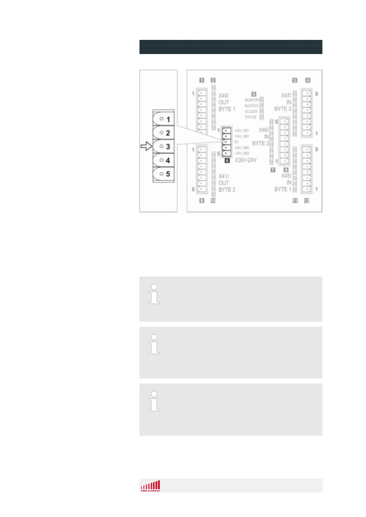
Fig. 15: Reference pin power connector
n Each byte is connected with an 8 pole terminal block.
n Each output byte has its own power supply connection.
This feature can be used to turn off a whole byte using an
external switch.
n The outputs are always referenced against 0 V, located in the
power connector (X30 pin 3 Fig. 15).
The current limitation of each output is 0.7 - 2.5 A per
pin in case of short circuits.
– Consider that the power supply cable for one
output byte has to be chosen accordingly.
Each output has a nominal output capability of 1 A.
Nevertheless each output byte (8 signals) is globally
limited to 4 A.
– Take care of this specification by appropriate
output definition toward the external actuator.
Outputs are monitored for faults. In case of errors, the
output is switched off.
Since every 4 adjacent outputs have a common status
signal, the onboard monitor always switches off 4 out-
puts in such a case (1 - 4, 5 - 8, 9 - 12, 13 - 16).
Connection
PA 8000 EL CNC control unit
Design and function
24.09.2015 | 38
 Loading...