Power Meter Bulletin No. 3020IM9503R6/98
Chapter 3—Hardware Description December 1998
10 1998 Square D All Rights Reserved
POWER METER CONNECTIONS
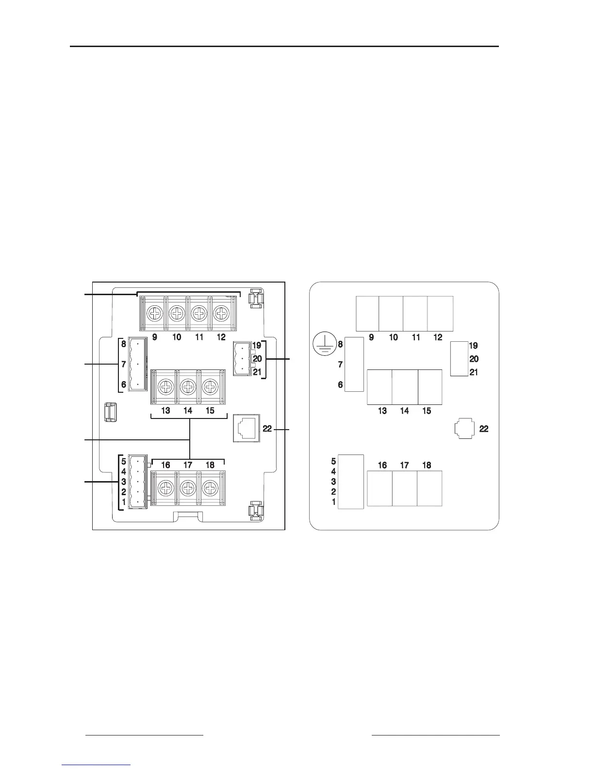
Figure 3-3 shows the front of the power meter and the label on the terminal
shield. Identified parts are as follows:
➀ 3-Phase Voltage Inputs
➁ Control Power Terminals
➂ KYZ Pulse Output
➃ 3-Phase Current Inputs
➄ Display Communications Port
➅ RS-485 Communications Terminals
Note: See Chapter 5—Wiring for wiring instructions.
Figure 3-3: Front of power meter and terminal shield label
Va Vb Vc Vn
Ia– Ib– Ic–
Ia+ Ib+ Ic+
IN+
IN–
OUT+
OUT–
SHLD
G
L
2
L
1
K
Y
Z
➅
➃
➁
➀
➂
➄