Power Meter Bulletin No. 3020IM9503R6/98
Appendix D—Additional Wiring Diagrams December 1998
76 1998 Square D All Rights Reserved
Load
Line
L1
N
L2
VDS
Fuses
Voltage
Control
Power
Comms
Current
Display
Communications
Port
KYZ
Top
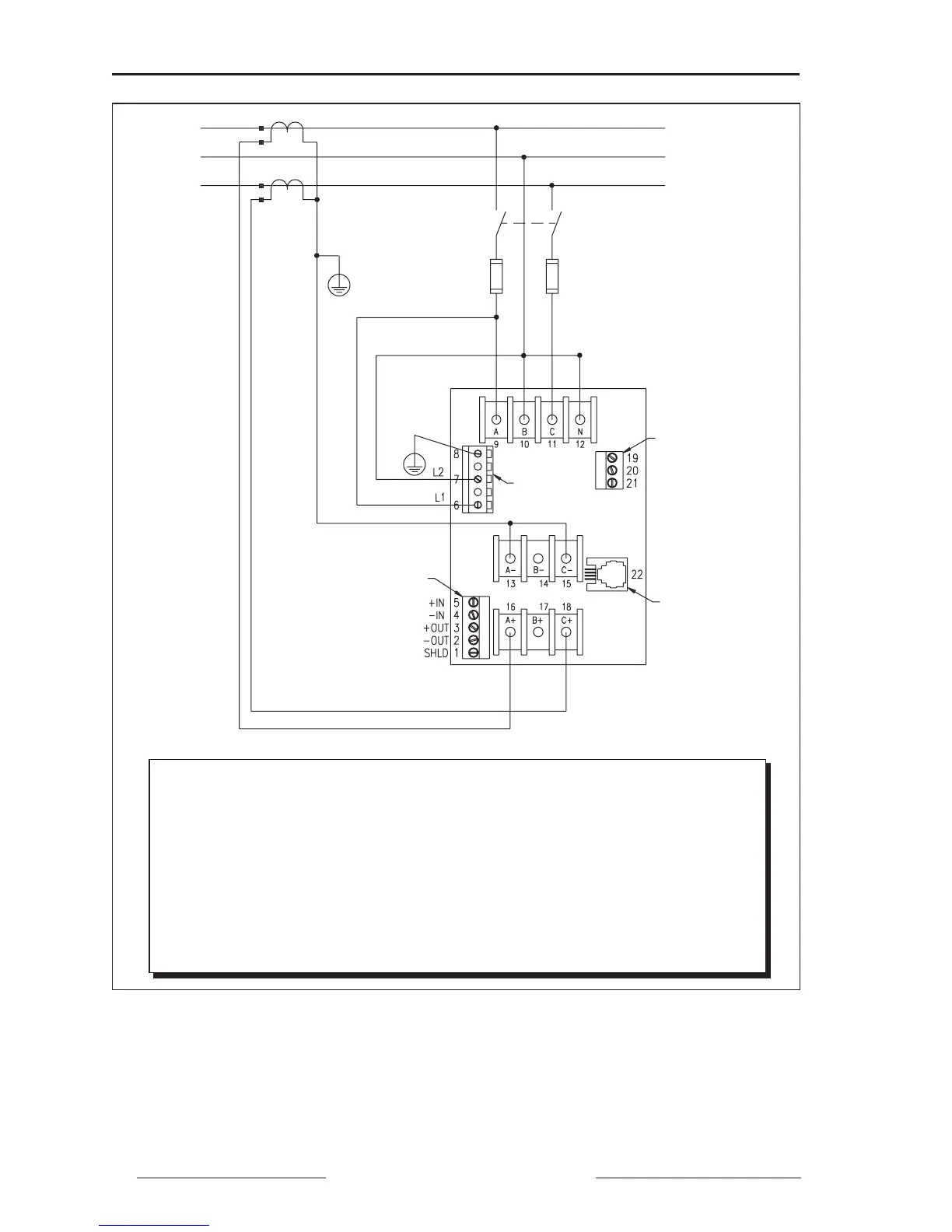
Figure D-1: 240/120 V 1-phase, 3-wire direct voltage connection with 2 CTs
Note: Control power can be drawn from fused voltage inputs L-L, or L-N, or an
external source. See page 22 for CPT and fuse recommendations.
Control power range: L1-L2 90–600 Vrms
90–300 Vdc
When configuring the power meter, set system type to 4-wire (40) and
PT ratio to 120:120.
Installation Category II