Bulletin No. 3020IM9503R6/98 Power Meter
December 1998 Chapter 6—Communications
1998 Square D All Rights Reserved 37
Connecting to a POWERLOGIC Network Interface Module (PNIM)
Using POWERLOGIC Communications
• Connect up to 32 PM&CS devices to a PNIM. See Length of the Communi-
cations Link in this chapter for distance limitations at different baud rates.
• Connect PM&CS devices to PNIM port 0 (top RS-485 port) only.
• Configure PNIM port 0 for “POWERLOGIC” mode (see side of PNIM for
instructions on setting dip switches).
• Configure the baud rate of PNIM port 0 to match the baud rate of the
PM&CS devices on the communications link.
• Refer to the PNIM instruction bulletin for detailed instructions on
configuring the PNIM.
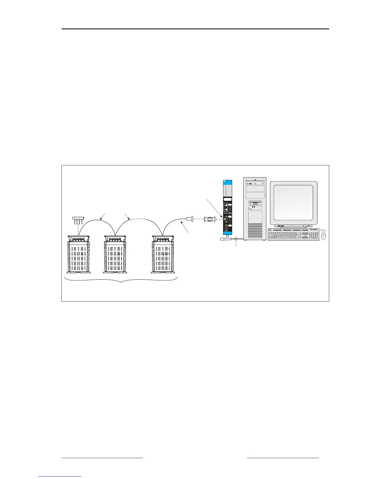
Figure 6-2: Power meters connected to a PNIM
SY/MAX
NETWORK
R x Ø
T x Ø
R x 1
T x 1
NET RxERROR
NET TxERROR
POWER
NETWORK
INTERFACE
NUMBER
NETWORK
INTERFACE
NUMBER
C
O
M
M
C
O
M
M
1——
Ø1 —
——
CLASS 8030
TYPE CRM-565
SY/NET
NETWORK
INTERFACE
2
8
1–32 Devices (Power Meters and Other Power
Monitoring & Control System Compatible Devices)
PC with SY/LINK Card
Belden 8723
(or equivalent)
CAB-107
MCA-485
Only Connect
Power Meters
to Top Port (Port 0)
of PNIM
SY/NET
(Belden 9463 or equivalent)
PNIM
MCTAS-485
(or MCT-485
with Terminal
Block)