Bulletin No. 3020IM9503R6/98 Power Meter
December 1998 Chapter 6—Communications
1998 Square D All Rights Reserved 43
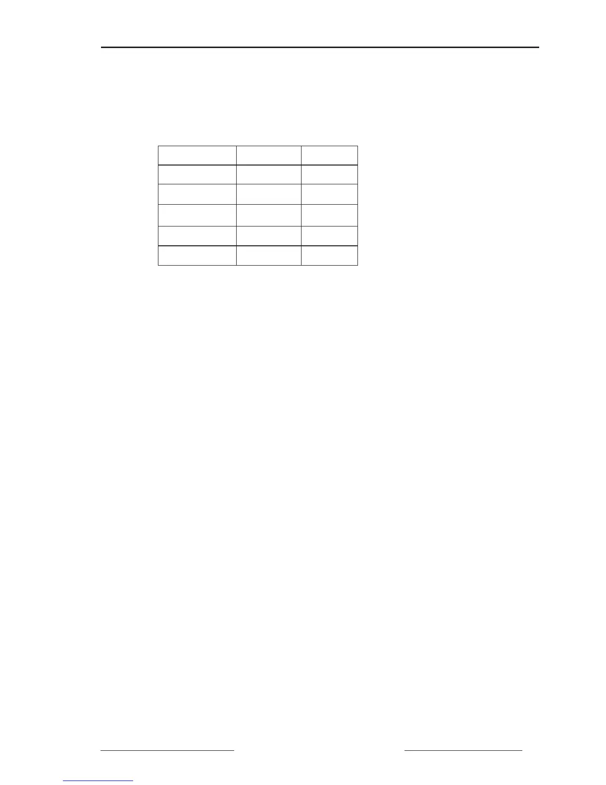
3. Carefully mark the flying leads on the CAB-107 as indicated in table 6-2
below. For example, mark the green wire, labeled 20, as “IN+”; mark the
white wire, labeled 21, as “IN–”; and so on.
4. Attach the male DB-9 connector on the CAB-107 to the multipoint
communications adapter.
5. Connect the CAB-107 spade connectors to the 5-position terminal block.
See figure 6-8, page 45, for terminal identification.
6. Cut a length of Belden 8723 (or equivalent) cable that is long enough to
reach from the terminal block to the first power meter. Strip back the
cable sheath 1-1/4" (32 mm) from both ends.
7. On one end of the Belden 8723 (or equivalent) cable, carefully strip .25"
(6 mm) of insulation from the end of each wire to be connected. Using a
suitable crimping tool, securely attach a forked terminal (spade connec-
tor) to each wire.
8. Connect the cable end with attached spade connectors to the terminal
block. See figure 6-8, page 45, for terminal identification. Tighten all
terminal screws to 6–9 lb-in (0.68–1 N•m).
9. On the other cable end, carefully strip .4"–.45" (10–11 mm) of insulation
from the end of each wire to be connected.
10. Connect this end of the Belden 8723 (or equivalent) cable to the power
meter RS-485 terminals; see figure 6-8, page 45, for communications
terminal identification.
Be sure to connect the terminal accepting the IN–
wire on the CAB-107 to the IN– terminal on the power meter, the terminal
accepting the IN+ wire on the CAB-107 to the IN+ terminal on the power
meter,
and so on. Tighten the RS-485 terminal screws to 5–7 lb-in
(0.56–0.79 N•m).
Note: An alternative to using a terminal block and a CAB-107 is to build a
custom cable using Belden 8723 cable (or equivalent) and a male DB-9 connector.
When building a cable, follow the CAB-107 pinout shown in Appendix C.
Existing Label Wire Color Mark As
20 Green IN+
21 White IN–
22 Red OUT+
23 Black OUT–
24 Silver SHLD
Table 6-2
Labeling the CAB-107 Leads