Chapter 5 Function parameter
73
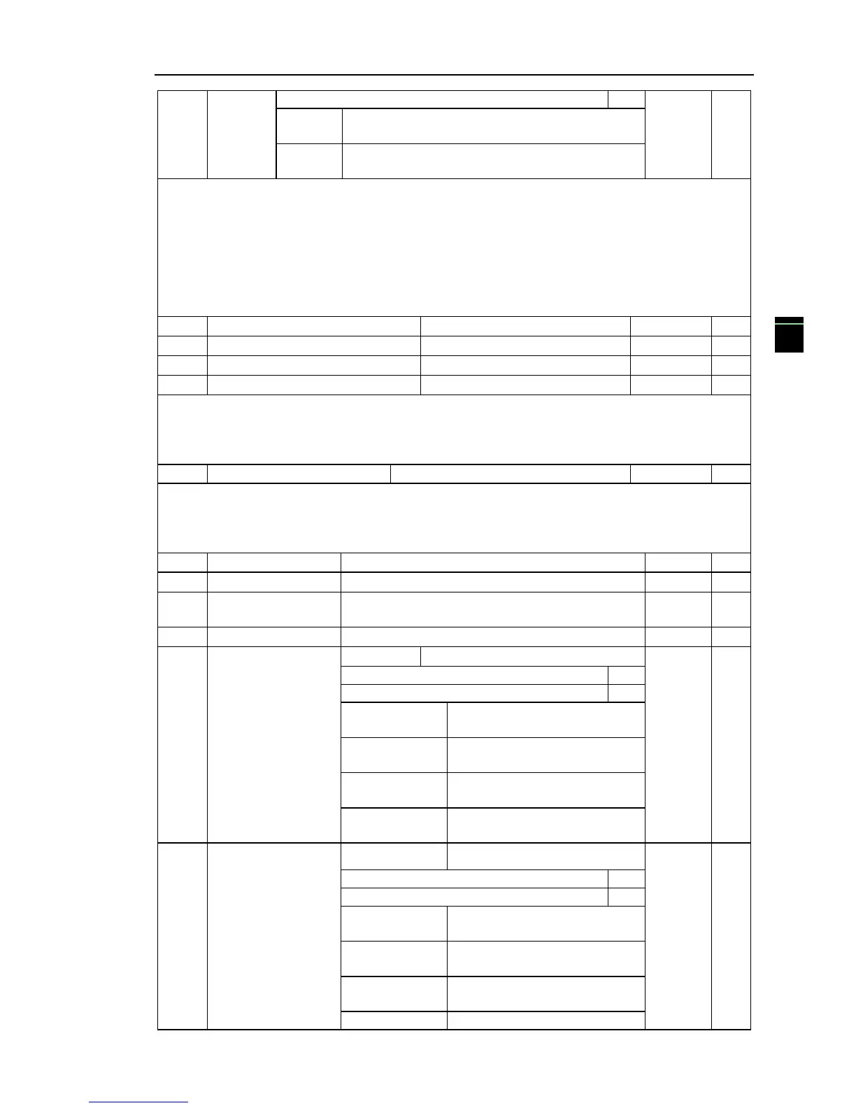
Setting selection for AI2 less than minimum
input(0 to 1, ditto)
Setting selection for panel potentiometer less than
minimum input(0 to 1, ditto)
The function code is used to set analog quantity and its corresponding setting when the
analog input voltage is less than the set Minimum Input.
Units digit, tens digit and hundreds digit the function code respectively correspond to the
analog input AI1, AI2, panel potentiometer. If 0 is selected, when the analog input is less than the
Minimum Input, the setting corresponding to the analog amount is the setting of minimum input of
the function code curve (F1.13, F1.17, F1.21).
If 1 is selected, when the analog input is less than the minimum input, the setting
corresponding to the analog amount is 0.0%.
F1.26 Corresponding to the set
F1.28 Corresponding to the set
This group function code is used to set the relationship between DI5 pulse frequency and its
corresponding setting.
Pulse frequency can be inputted into the inverter only through DI5 channel. The application
on this group of functions is similar to curve 1, please refer to the description of curve 1.
Set software filter time for DI terminals status. For the application that input terminals are
vulnerable to interference and cause the accidental operation, you can increase this parameter so as
to enhance the anti-interference ability. However, the increase of filter time will cause DI terminal
slow response.
Panel encoder/AI3
filter time
DI terminal Mode
Selection 1
DI1 Terminal active state set
DI2 Terminal active state set
(0~1,same as the units digit)
DI3 Terminal active state set
(0~1,same as the units digit)
DI4 Terminal active state set
(0~1,same as the units digit)
DI5 Terminal active state set
(0~1,same as the units digit)
DI terminal mode
selection 2
DI6 Terminal active state set
DI7 Terminal active state set
(0~1,same as the units digit)
DI8 Terminal active state set
(0~1,same as the units digit)
DI9 Terminal active state set
(0~1,same as the units digit)
DI10 Terminal active state set

 Loading...


