PreciseFlex_Robot
112
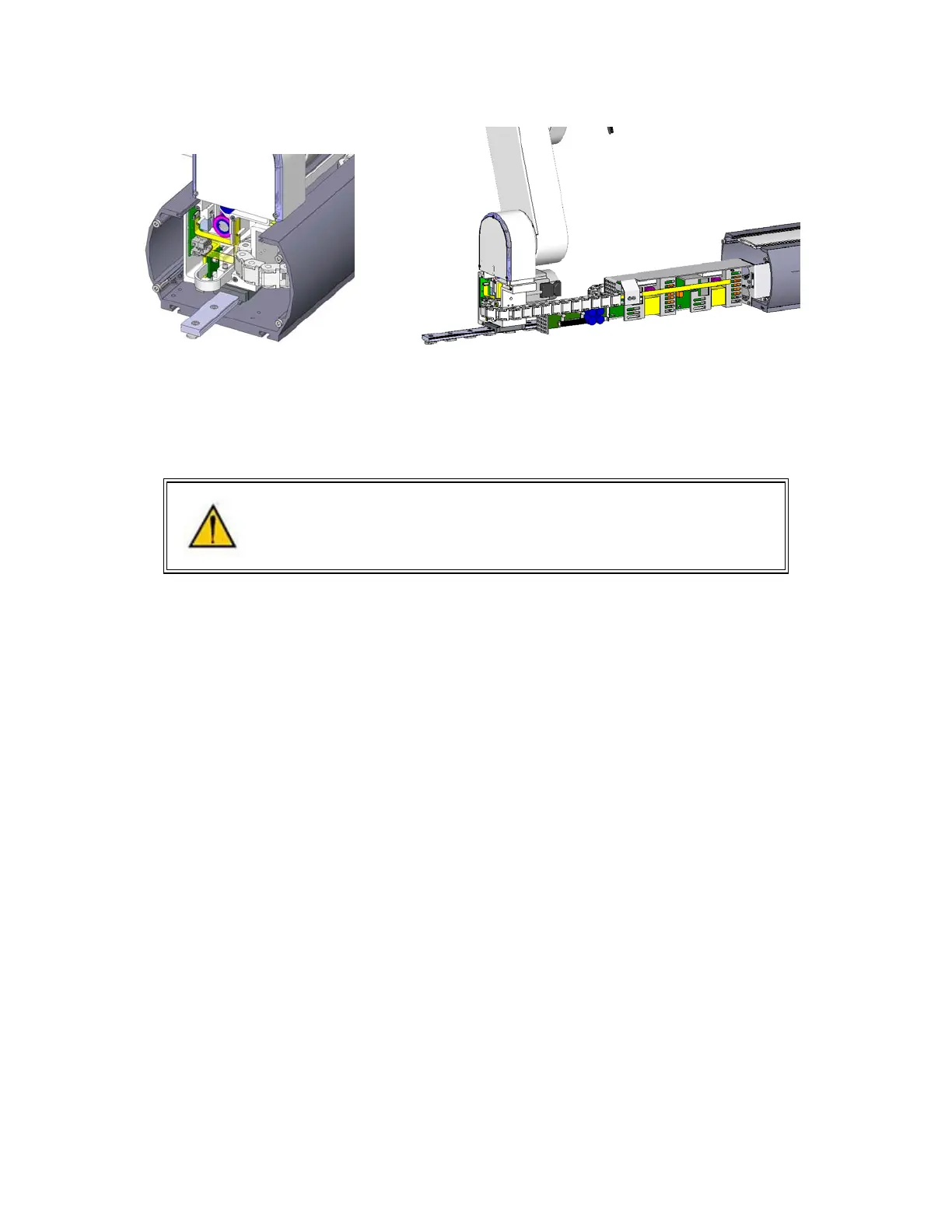
Replacing the Robot Controller
DANGER: Before replacing the Robot Controller, the AC power should be
removed.
Tools Required:
1. 2.5mm hex driver or hex L wrench
2. 2.0mm hex driver or hex L wrench
3. Small flat bladed screw driver, with 1.5mm wide blade typ
4. M5 socket driver or M5 open end wrench or pliers
Spare Parts Required:
1. Guidance G1400B Controller PN P/N G1X0-EA-B1400-1
Prior to replacing the controller, the user may wish to make copies of both the robot PAC files, and any
project files to a PC, using a procedure similar to that described for loading a project in the Software
Reference Section.
To replace the Robot Controller the user must:
1. Turn off the robot power and remove the AC power cord.
2. Remove the Inner Link Cover by removing the 4 M3 X 20 SHCS that attach the cover.
3. Remove the upper circuit board by removing 4 M2.5 X 6mm screws.
4. Unplug the cables from upper circuit board
5. Remove the lower circuit board by removing 4 M2.5 X 16mm standoffs with an M5 socket driver.
6. Unplug the cables from the lower circuit board. Use a small flat bladed screwdriver to gently
release the 3 zero-insertion-force (ZIF) flat flexible cable (FFC) connector compression lids.
7. Check the jumpers on the replacement CPU board (top board) per the photo below.
8. Re-attach the harness and replace the circuit boards. Refer to the schematics section above for
connector labeling on the circuit boards. Be careful that the 2 pin plug from the brake release
switch plugs into the lower board and the 2 pin plug on the pigtail from the lower board plugs into