81
5. Then in step 4 in the menu click on either FPGA or GPL to upgrade the appropriate file. The
banner in the Upgrade menu will start flashing for about 10 seconds while the flash RAM is being
written with the new file. Wait about 10 additional seconds after this banner stops flashing, then
reboot the robot, and the new code will be installed.
Recovering from Corrupted PAC Files
PAC files are configuration files that determine the configuration of the robot for the software, including
the robot factory calibration data. These files are stored in Flash RAM. Flash RAM is also used to store
robot programs. The Flash RAM requires some time for a complete write cycle. During the write cycle,
the console will display a flashing warning not to turn off robot power. If robot power is turned off during
the Flash RAM write cycle, the Flash data may be lost or corrupted. If this happens, it is necessary to
reload both the robot PAC files and any user programs that were stored in Flash RAM. This problem
should typically not be encountered by a user unless the user is changing configuration files in the robot.
Precise maintains a record of PAC files shipped with each robot Serial Number. If the PAC files have
been corrupted, it is possible to get a back up copy from Precise. The backup copy will contain the
factory configuration and calibration data, but will not contain any changes, including any new calibration
data, made after the robot has left the factory.
In order to allow the controller to recover from corrupted PAC files, a set of recovery boot up PAC files is
loaded in a the system area of the Flash.
To configure the controller to boot up in recovery mode the user must:
1. Obtain a set of backup PAC Files from Precise or local backup.
2. Remove the Inner Link Cover of the robot.
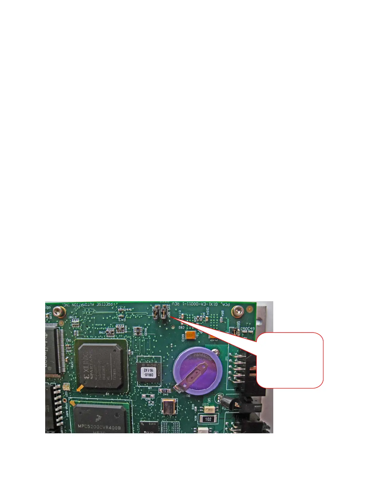
3. Move Jumper J8 (see figure below) so that it connects the two jumper posts. This will cause the
factory default configuration files to be loaded at controller boot up.
System Reset
Jumper. Move to
connect posts
1&2. Newer PCAs
have 3 pins. Pin 3
is not connected.