89
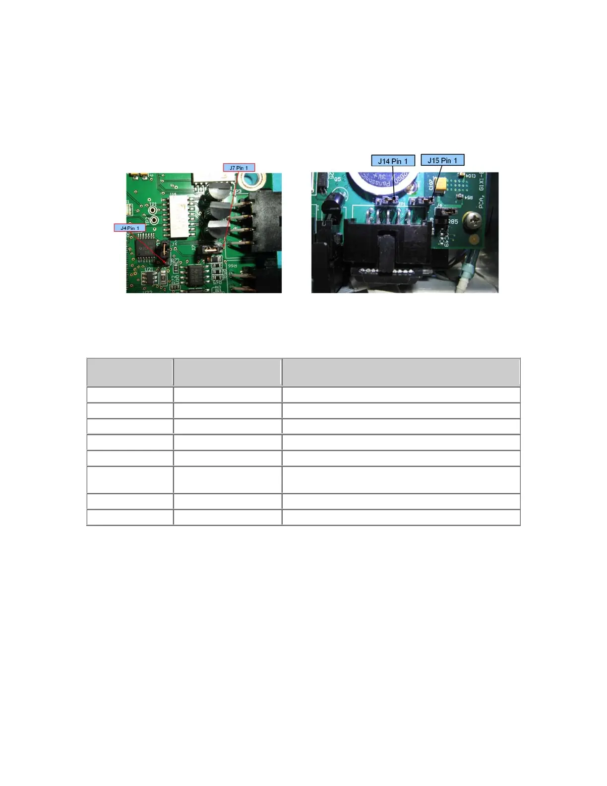
must be correctly installed to connect RS232 to the GSB. On the CPU board, shown below, J14 and J15
must be connected to pins 2 and 3 to connect the TXD and RXD inputs from the GSB to the serial inputs
in the CPU. The factory configuration for J14 and J15 is connecting pins 1 and 2. This is because prior
to Rev 4 of the GSB, the wires connected to these pins in the RS485 cable were grounded, and if you
plug in a GSB earlier than Rev 4, you will ground the RS232 signals unless J14 and J15 are in their
factory configuration.
J4 and J7 on GSB Board J14 and J15 on CPU Board
The GSB I/O signals are shown in the table below:
Pin
GPL Signal
Number
Description
1 200013 Di
ital Output 1
2 200014 Di
ital Output 2
3 200015 Di
ital Output 3
LED Output or TXD, select with J7
4 24 VDC output
5 GND
6 210001
Digital Input 1 (Pushbutton on some Electric Grippers
or RXD, select with J4
7 210002 Di
ital Input 2
End of travel sensor option
8 210003 Di
ital Input 3
Optional Pneumatic or Vacuum Gripper
It is possible to order an optional pneumatic or vacuum gripper. In these cases there is no servo gripper
controller (GSB) board. The J4 motor FFC motor interface board is replaced by a vacuum/pneumatic
gripper interface board which includes 2 digital outpus, 2 digital inputs, and 1 or 2 analog inputs for a
vacuum sensor. The RS485 cable from the controller to the GSB board is removed. A different IO cable
is installed from the FFC interface board on the side of the inner link to the vacuum/pneumatic interface
board. This different cable routes the IO signals from the robot controller to the outer link.