PreciseFlex_Robot
134
17. Attach the J3 Harness Retaining Clip to the J3 Output Pulley.
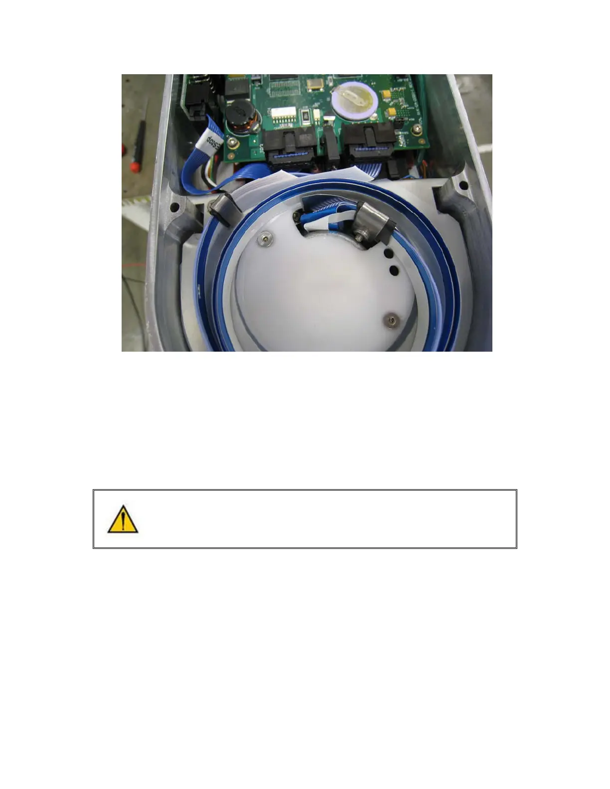
18. Attach the connectors to the circuit boards in the Outer Link.
19. Attach the J4 Motor Interface circuit board.
20. Replace the covers.
21. After replacing the harness the robot must be re-calibrated. See Calibrating the Robot.
Replacing the Z Axis Motor Assembly
DANGER: Before replacing the Z Axis Motor, the AC power should be removed.
Tools Required:
1. 5.0mm hex driver or hex L wrench
2. 4.0mm hex driver or hex L wrench
3. 3.0mm hex driver or hex L wrench
4. 2.5 mm hex driver or hex L wrench
5. Loctite 243
Spare Parts Required:
1. J1 Motor Assembly PN PF01-MA-00011.