115
1. Turn off the robot power and remove the AC power cord.
2. Remove the Outer Link Cover.
3. Remove the Gripper Controller by removing 4 M3 X 10mm SHCS and unplugging the cables.
4. Replace the Gripper Controller and re-attach the harness.
5. Replace the Outer Link Cover.
6. It is not necessary to recalibrate the robot after replacing the Gripper Controller.
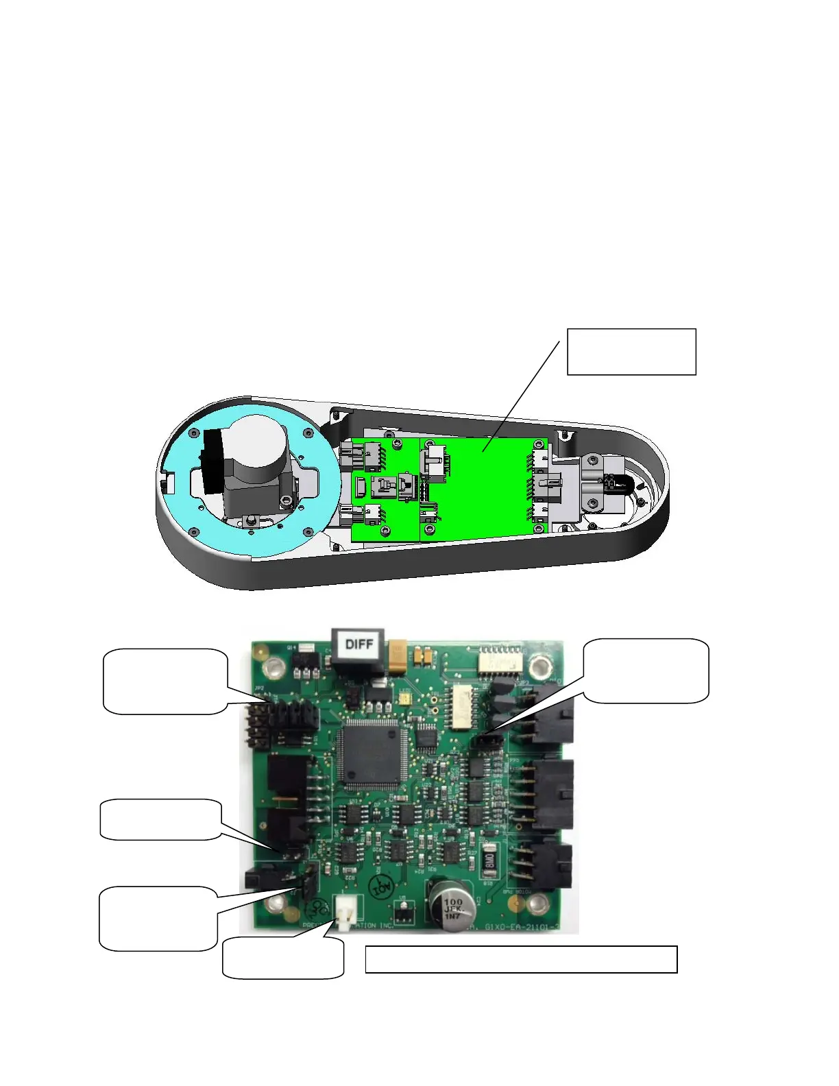
7. Starting January of 2013 gripper controllers are a new rev (GSB3), which replaces the address
DIP switch with jumpers. To make the SW in the GSB3 work in a compatible mode with the
standard PAC files, Jumper J11 must be removed.
8. In the case of the controller for the 60N gripper, the battery pigtail must be attached, with the
positive red wire soldered to pin 1 and the black wire soldered to pin 2of the white Molex
connector on the GSB controller, with shrink tube to insulate the wires, and the leads must be
bent over to clear the cover.
J3 jumper
pins 1 & 2
(Connect 24V)
J8, J9, J10
installed. J11
removed
Install J6
J7 jumper
pins 2 & 3
(LED resistor)
Battery
Not used
Gripper Controller Rev 2
GSB3
umpers
Gripper
Controller