PreciseFlex_Robot
144
6. Rotate the Outer Link clockwise (viewing from above) until it hits the hard stop. This will expand
the harness coil and the link will be position as shown below, about 10 degrees from straight out.
7. Remove the J4 Motor Interface Board in the Outer Link and unplug the cables.
8. Remove the Outer Link by removing 6 M3 X 35 SHCS in the J3 Output Pulley that attach the
Outer Link.
9. Remove the Gripper Controller by unplugging the Gripper harness and removing 4 M3 X 8 SHCS.
10. Remove the Outer Link Belt Cover by removing 4 M3 X 10 SHCS.
11. Remove the J4 motor by removing the 2 M4 Screws attaching the motor to the motor mount
plate, and rotate the motor up and out of the motor mount plate. This procedure will preserve the
belt tension and avoid having to use a tension meter to reset the belt tension, as it preserves the
position of the motor mount plate.
12. Replace the J4 motor, using Loctite 243, or optionally, replace the J4 timing belt if necessary.
Since the motor mount plate has not been removed, the belt tension should not need to be
adjusted.
13. If a Belt Tension Meter is available, check the belt tension per Appendix D. Check the belt
tension every 10 degrees of rotation of the J4 output pulley and set the belt tension at its lowest
point to the minimum value in Appendix D.
14. Replace the pulley mount plate using Loctite 222 and re-assemble the robot, with the outer link
positioned as shown above so that the link is correctly oriented with respect to the hard stop.
15. Re-calibrate the robot.
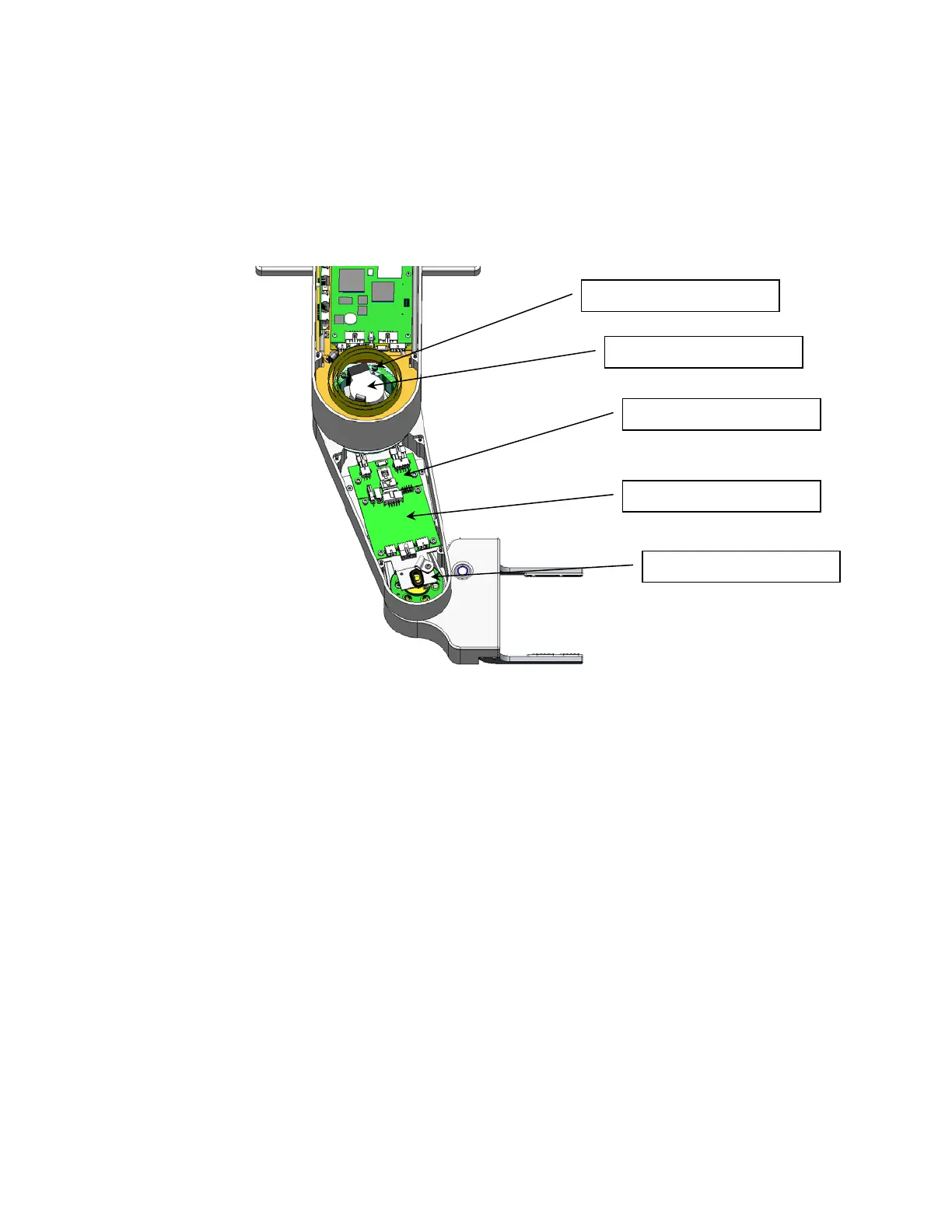
6 ea M3 X 35 SHCS
Gripper Controller
Outer Link Belt Cover
J4 Motor Interface PCA
J4 Motor