Model PD6000 Analog Input Process Meter Instruction Manual
Signal Connections
Signal connections are made to a five-terminal connector labeled
SIGNAL on Figure 5. The COM (common) terminal is the return for the
4-20 mA and the ±10 V input signals.
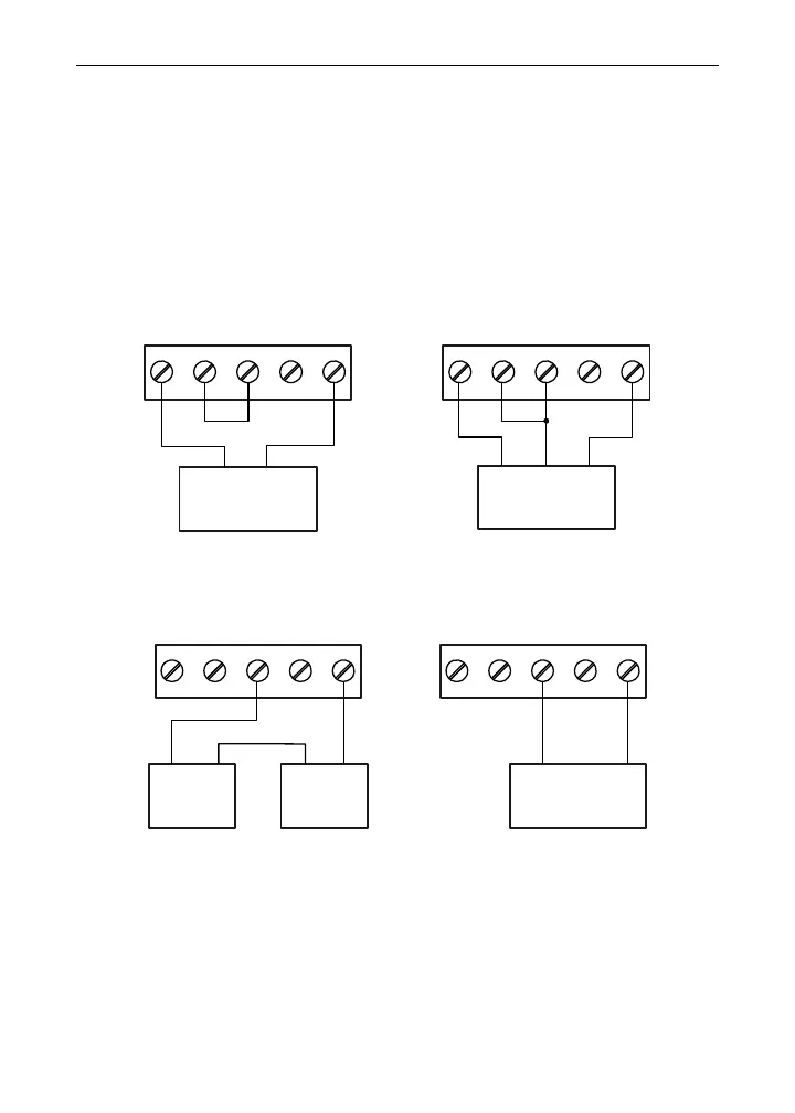
Current and Voltage Connections
The following figures show examples of current and voltage connections.
There are no switches or jumpers to set up for current and voltage inputs.
Setup and programming is performed through the front panel buttons.
-+
mA+P-
2134
P+ V+
COM
INPUT SIGNAL
3-Wire 4-20 mA
Transmitter
5
Signal
+-
2-Wire
4-20 mA
Transmitter
mA+P-
21354
P+ V+
COM
INPUT SIGNAL
Figure 7. Transmitters Powered by Internal Supply
19
+--+
External
Power
Supply
2-Wire
4-20 mA
Transmitter
mA+P-
21354
P+ V+
COM
INPUT SIGNAL
-+
mA+P-
2134
P+ V+
COM
INPUT SIGNAL
2-Wire 4-20 mA
Self-Powered
Transmitter
5
Figure 8. Transmitter Powered by Ext. Supply or Self-Powered
The current input is protected against current overload by a resettable
fuse. The display may or may not show a fault condition depending on
the nature of the overload.
The fuse limits the current to a safe level when it detects a fault condi-
tion, and automatically resets itself when the fault condition is removed.