Model PD6000 Analog Input Process Meter Instruction Manual
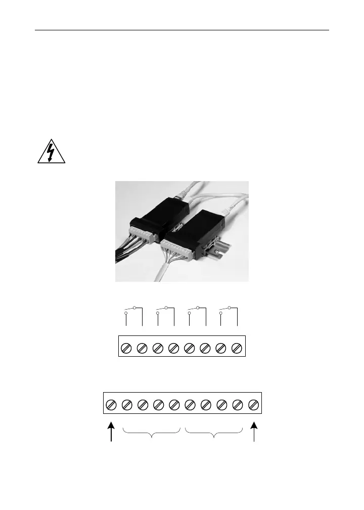
External Relays & Digital I/O Connections
The relay and the digital I/O expansion modules PDA1004 & PDA1044
are connected to the meter using a CAT5 cable provided with each
module. The two RJ45 connectors on the expansion modules are iden-
tical and interchangeable; they are used to connect additional modules
to the system.
Note: The jumper located between the RJ45 connectors of the
PDA1044 must be removed on the second digital I/O module in
order for the system to recognize it as module #2.
Warning!
Do not connect or disconnect the expansion modules with
the power on!
More detailed instructions are provided with each optional
expansion module.
Figure 14. Expansion Modules & DIN Rail Mounting Kit
12
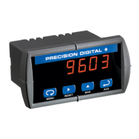
RLY5 RLY6 RLY7 RLY8
345678
NO C NO C NO C NO C
Figure 15. External Relays Module Connections
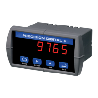
123456
+5 I1 I2 I3 I4 O1
78
O2 O3
910
O4 G
DI 1-4 DO 1-4
5 VDC GND
Figure 16. Digital I/O Module Connections
23