2.Disassembly
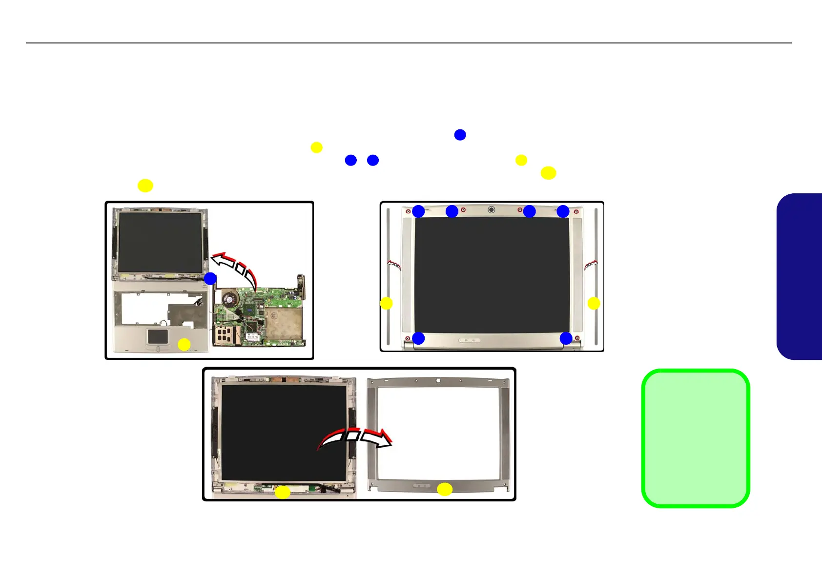
Removing the LCD Front Panel Module
1. Turn off the computer and remove the battery (page 2 - 7), HDD (page 2 - 8), RAM (page 2 - 10), optical device
(page 2 - 11), WLAN module (page 2 - 12), processor (page 2 - 13), keyboard & shielding plate (page 2 - 15), sep-
arate the top & bottom cases (page 2 - 17), and disconnect any Bluetooth antenna cable (page 2 - 19).
2. Very carefully ease each individual cable through top case assembly at point .
3. Lift the LCD assembly off the top case module .
4. Remove all the rubber covers and screws from points - , and the rubber side covers .
5. Run your finger around the middle of the frame to carefully unsnap the LCD front panel module from the LCD
assembly .
1
2
3 8 9
10
Figure 2 - 15
Removing the LCD
Front Panel Module
a. Carefully ease out the
cables and separate the
LCD assembly from the
top case module.
b. Remove the rubber cov-
ers and screws.
c. Separate the LCD front
panel module from the
LCD assembly.
2. Top Case Module
9. 2 * Rubber Side
Covers
10. LCD Front Panel
11. LCD Assembly
•6 Screws &
Rubber Covers
3
a. b.
9
11
1
4 5 6
8 7
9
c.
2
10
11
TECHNICAL SERVICE MANUALPrestigio Visconte 125W
21