516514 23
To reduce the risk of electric shock, fire, explosion, serious injury or death:
• Disconnect electric power to the dryer(s) before servicing.
• Close gas shut-off valve to gas dryer(s) before servicing.
• Never start the dryer(s) with any guards/panels removed.
• Whenever ground wires are removed during servicing, these ground wires must be
reconnected to ensure that the dryer is properly grounded.
W001R1
WARNING
© Copyright, Alliance Laundry Systems LLC – DO NOT COPY or TRANSMIT
Section 5
Service Procedures
IMPORTANT: When reference to direction (right
or left) is made in this manual, it is from the
operator’s position facing the front of the dryer.
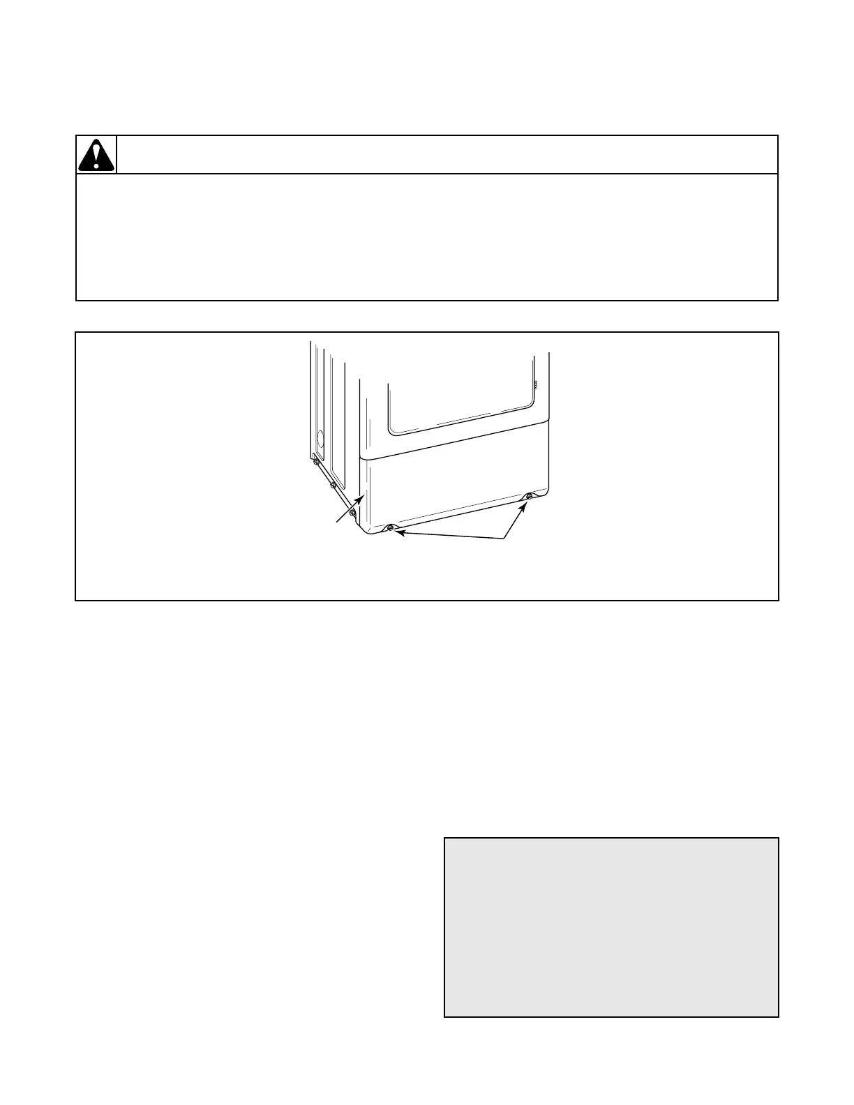
19. ACCESS PANEL
(Figure 7)
a. While supporting the access panel, remove two
screws from bottom edge of access panel.
b. Gently lower the access panel to disengage
locators from bottom edge of front panel.
c. Remove access panel.
20. CONTROL PANEL AND CONTROLS
(METERED AND NONMETERED)
(Figure 8)
a. Remove two control panel attaching screws and
lay panel face down on protective padding on
cabinet top.
b. Disconnect all wires to fabric selector switch,
push-to-start switch and indicator light and
remove ground clip and screw holding ground
wire to cabinet top and control panel.
NOTE: Refer to wiring diagram when reconnecting
wires.
c. Loosen setscrew holding switch knob to shaft
and pull knob off shaft.
d. Remove knurled nut holding fabric selector
switch to panel and remove switch.
e. Remove hex nut from push-to-start switch and
remove switch.
f. Squeeze locking tabs on indicator light and pull
light out from back of panel.
Figure 7
ACCESS
PANEL
PANEL
ATTACHING
SCREWS
D302SE3B
To Test Push-to-Start Switch
1. Unplug dryer from electrical supply and
disconnect wires from switch terminals.
2. Set Volt-Ohm meter on OHMS scale and
calibrate at appropriate scale.
3. Place meter probes on switch terminals. You
should see an “infinite” reading on the meter.
4. With probes attached to switch, press the start
switch button. Meter should read “0” Ohms.