516514 25
Section 5 Service Procedures
To reduce the risk of electric shock, fire, explosion, serious injury or death:
• Disconnect electric power to the dryer(s) before servicing.
• Close gas shut-off valve to gas dryer(s) before servicing.
• Never start the dryer(s) with any guards/panels removed.
• Whenever ground wires are removed during servicing, these ground wires must be
reconnected to ensure that the dryer is properly grounded.
W001R1
WARNING
© Copyright, Alliance Laundry Systems LLC – DO NOT COPY or TRANSMIT
21. GRAPHIC OVERLAY
(Figure 8)
a. Removal
(1) Remove twocontrolpanel attaching screws
and lay panel face down on protective
padding on cabinet top.
(2) Loosen setscrew holding switch knob to
switch shaft. Refer to Figure 8.
(3) Remove knurled nut holding fabric selector
switch to panel.
NOTE: Lockwasher must be between fabric
selector switch and control panel when installing
switch. Refer to Figure 8.
(4) Remove hex nut from push-to-start switch.
(5) Disconnect wires from switches and
indicator lights.
NOTE: Refer to wiring diagram when rewiring
switches and indicator light.
(6) Remove control panel overlay by peeling it
from control panel frame.
NOTE: Control panel overlay has an adhesive
backing.
b. Installation
NOTE: Before removing protective backing from
new overlay, check fit of overlay to control panel
frame. Switch holes are the locating guides.
(1) Once panel overlay is fitted to the front of
control panel frame, carefully peel
protective backing from the left end of
panel overlay and press into place.
(2) Remove rest of protective backing from
panel overlay and firmly press overlay into
place on control panel frame.
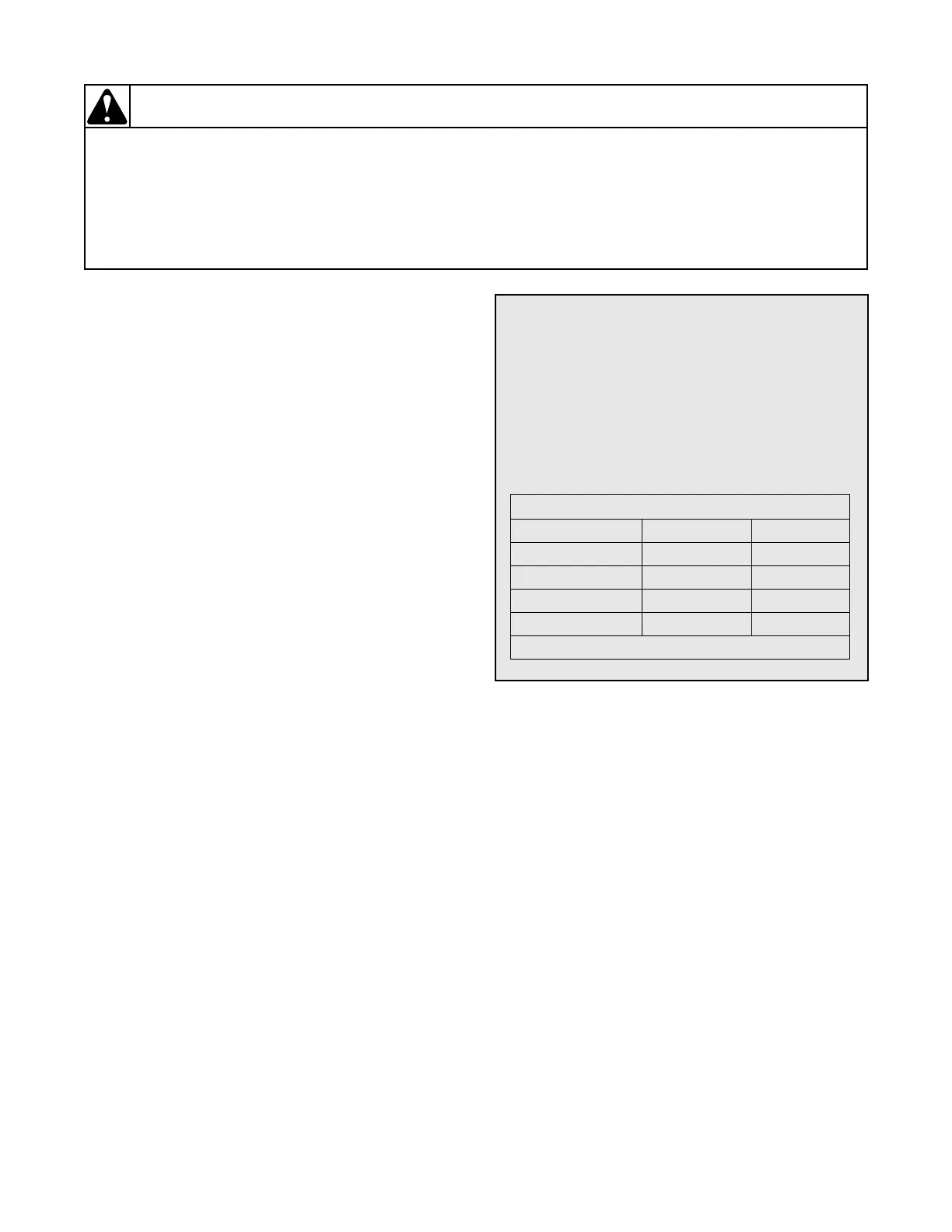
To Test Fabric Selector Switch
NOTE: Refer to proper model wiring diagram
when rewiring switch.
1. Set test meter to read Ohms and apply meter
probes to switch terminals.
NOTE: Refer to proper model wiring diagram
when reconnecting wires.
FABRIC SELECTOR SWITCH – 4 Position
L1-1 L1-2
Fluff – –
Delicate X X
Perm. Press – X
Normal – X
X indicates closed