516514 37
Section 5 Service Procedures
To reduce the risk of electric shock, fire, explosion, serious injury or death:
• Disconnect electric power to the dryer(s) before servicing.
• Close gas shut-off valve to gas dryer(s) before servicing.
• Never start the dryer(s) with any guards/panels removed.
• Whenever ground wires are removed during servicing, these ground wires must be
reconnected to ensure that the dryer is properly grounded.
W001R1
WARNING
© Copyright, Alliance Laundry Systems LLC – DO NOT COPY or TRANSMIT
26. METER CASE (Metered Models)
a. Remove two control panel attaching screws and
lay panel face down on protective padding on
cabinet top. Refer to Figure 8.
b. Disconnect all wires to components, and
remove ground clip and screw holding ground
wire to cabinet top and control panel. Refer to
Figure 4.
NOTE: Refer to wiring diagram when reconnecting
wires.
c. Insert key in service door lock on top of meter
case and unlock door. Refer to Figure 10.
d. Lift rear of service door approximately 45° off
meter case to disengage notched tabs with
internal rib at top of meter case. Refer to
Figure 10.
NOTE: When reinstalling service door, front end of
door must be inserted at about 45° angle in order to
engage notched tabs with internal rib at top of
meter case.
e. Disconnect wires from accumulator. Refer to
Figure 10.
NOTE: Refer to wiring diagram when reconnecting
wires.
f. Remove ground screw holding green ground
wire to accumulator mounting bracket. Refer to
Figure 10.
g. Remove two cap screws holding meter case to
cabinet top. Refer to Figure 25.
h. Remove nut, lockwasher and screw holding
meter case to right end of control hood. Refer to
Figure 8.
i. While supporting the access panel, remove two
screws from bottom edge of access panel. Refer
to Figure 7.
j. Gently lower the access panel to disengage
locators from bottom edge of front panel. Refer
to Figure 37.
k. Remove two screws holding bottom tabs on
front panel to dryer cabinet. Swing front panel
away from dryer to disengage hold-down clips
and locators from cabinet top. Refer to
Figure 37.
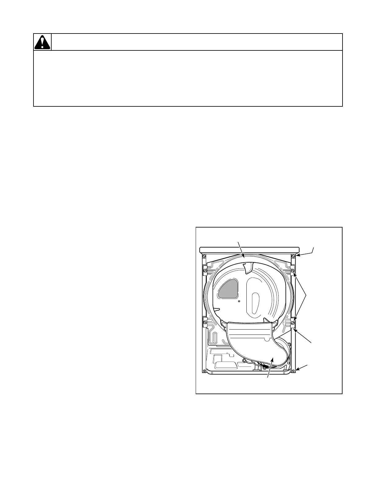
Figure 26
D394SE1A
BULKHEAD
ATTACHING
SCREWS
SLOT
CABINET
ATTACHING
SCREW
AIR
DUCT
CABINET TOP
HOLD-DOWN
SCREW
FRONT
BULKHEAD