54 516514
Section 5 Service Procedures
To reduce the risk of electric shock, fire, explosion, serious injury or death:
• Disconnect electric power to the dryer(s) before servicing.
• Close gas shut-off valve to gas dryer(s) before servicing.
• Never start the dryer(s) with any guards/panels removed.
• Whenever ground wires are removed during servicing, these ground wires must be
reconnected to ensure that the dryer is properly grounded.
W001R1
WARNING
© Copyright, Alliance Laundry Systems LLC – DO NOT COPY or TRANSMIT
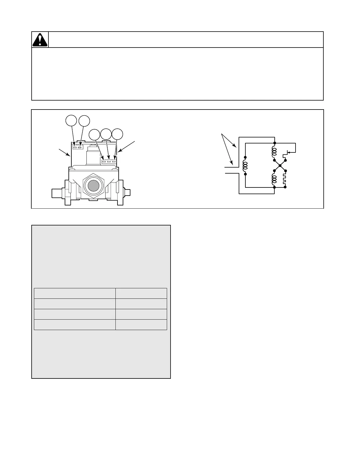
Figure 40
SECONDARY
COIL
HOLDING COIL
AND
BOOSTER COIL
(SPLIT COIL VALVE)
4
1
5
2 3
D267SE3B
SENSOR
SECONDARY
COIL
HOLDING
COIL
BOOSTER
COIL
IGNITER
120 VOLT, 60 HERTZ
ELECTRICAL
SUPPLY LINE
D268SE3A
To Test Gas Valve Coils
(Gas Models)
1. Remove disconnect blocks from gas valve coils.
2. Set test meter to read Ohms and put meter
probes to terminals shown in Figure 40,andin
the following chart.
SILICON CARBIDE IGNITION:
Coil Tolerance Readings
SILICON NITRIDE IGNITION: Both coils should
read between 2400 - 2800 Ohms.
NOTE: If meter registers any other readings than
those listed above, the respective coil(s) should be
replaced.
Meter probes to terminals: Meter should read:
Holding Coil – Terminals 1 & 2 1365 ± 25 Ohms
Booster Coil – Terminals 1 & 3 560 ± 25 Ohms
Secondary Coil – Terminals 4 & 5 1220 ± 50 Ohms