6 "Level switch" terminal
7 "CAN bus" socket (external)
8 LEDs (as Fig. 5) and CAN bus status LED (external)
not shown Stroke length adjustment wheel
4.1 Control elements
Use this overview to familiarise yourself with the keys
and the other control elements on the pump!
12012
12000
CONTACT
memory
l/h
CAN
open
hh
B1087
1
3
2
Fig. 7: Construction of continuous display
1 Status bar
2 Continuous display, central area
3 Secondary display
Refer to the chapter entitled "Main displays and secondary displays" in the
Appendix for the different main displays and secondary displays.
The LCD screen supports the operation and adjustment of the pump by
providing different information and identifiers:
120120
12000
Dosing monitor!
CONTACT
memory
l/h
CAN
open
hh
12000
ANALOGUE
hh
Input signal < 4 mAInput signal < 4 mA
i < 4 mAi < 4 mA
B1088
a)
b)
i < 4 mA!
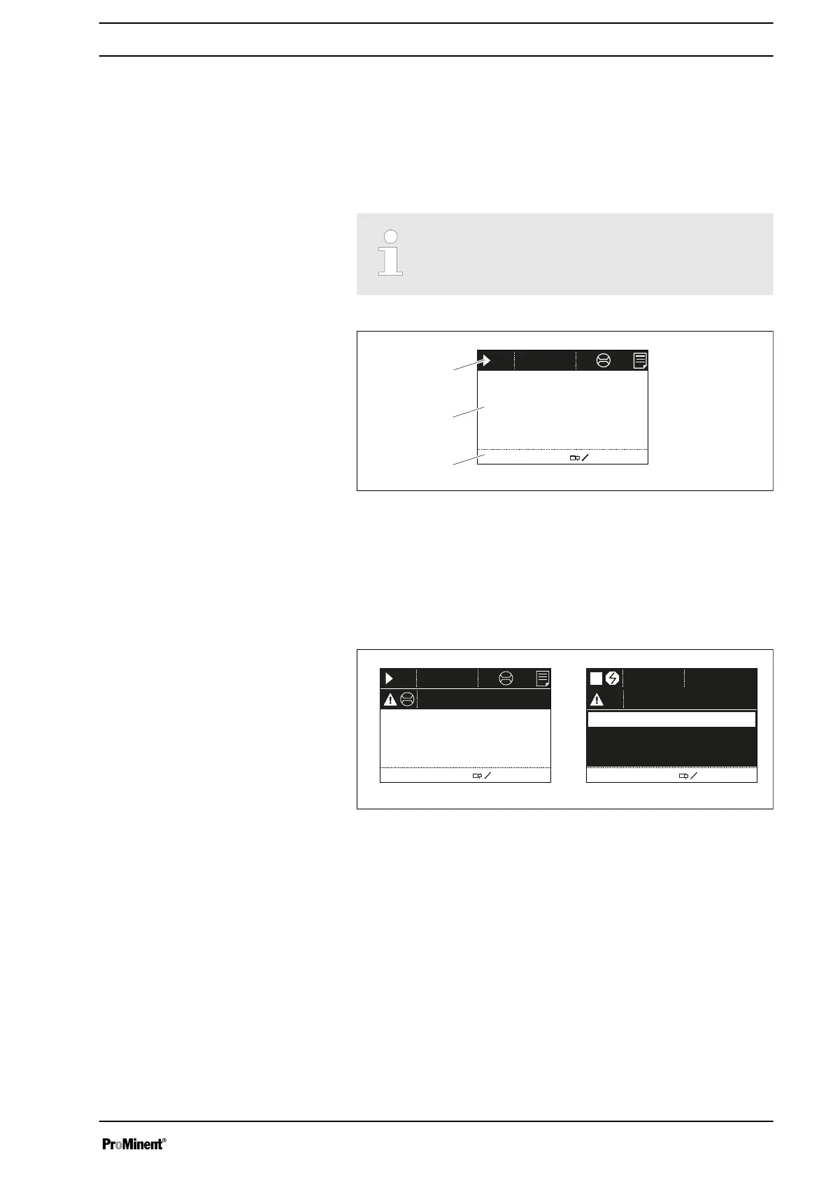
Fig. 8: a) Continuous display with warning message; b) Continuous display
with fault message. Explanation of the symbols in the following tables.
The above Figure, Part a) shows that:
n The pump is in operation
n Is in
‘Contact’
operating mode with "memory" stroke memory
n A metering monitor is connected
n A log entry has been made
n A warning message for the
‘metering monitor’
is pending
n The capacity of 12.0 l/h has been set
n The stroke rate is 12,000 strokes / h
Pressure display, identifier and fault dis‐
plays on the LCD screen
Overview of equipment and control elements
15