Configuring the MVI69E-MBTCP Using PCB MVI69E-MBTCP ♦ CompactLogix Platform
User Manual Modbus TCP/IP Enhanced Communication Module
Page 50 of 150 ProSoft Technology, Inc.
June 28, 2017
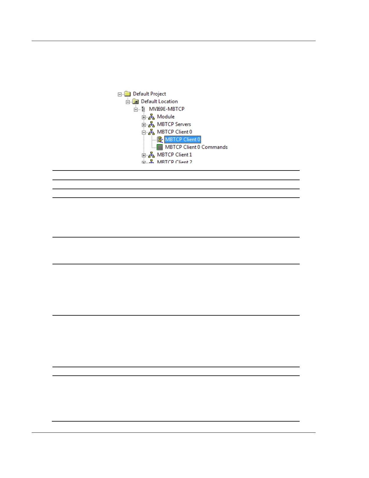
3.2.3 MBTCP Client x
This section defines the general configuration for MBTCP Client x. You can
configure up to 20 MBTCP clients, each using the parameters below. In the
ProSoft Configuration Builder tree view, double-click the MBTCP CLIENT X icon.
Specifies whether to start with commands active on boot up
Specifies the starting register location in the module’s database
for the error/status table for this client. If you enter a value of -1,
the error/status data is not placed in the database.
All other valid values determine the starting location of the data.
This data should be placed within the read data range of module
memory.
Specifies the address in the module’s database where the
command error data is placed. If you set the value to -1, the data
is not transferred to the database. This data should be placed
within the read data range of module memory.
Specifies the number of milliseconds to wait between receiving
the end of a server's response to the most recently transmitted
command and the issuance of the next command.
You can use this parameter to place a delay after each
command to avoid sending commands on the network faster
than the servers can be ready to receive them. It does not affect
retries of a command, as retries are issued when a command
failure is recognized.
Specifies the command response timeout period in 1 millisecond
increments. The client waits for a response from the addressed
server within the timeout period before re-transmitting the
command (Retries) or skipping to the next command in the
Command List.
The value depends on the communication network used and the
expected response time (plus or minus) of the slowest device on
the network.
Specifies the number of times a command is retried if it fails.
Specifies if the Daniel/ENRON-specific floating-point data access
functionality is to be implemented. If you set the Float Flag to Y,
Modbus functions 3, 6 and 16 interpret floating point values for
registers as specified by the two following parameters (Float
Start, Float Offset).
Note: You do not need to enable this parameter for most
applications using floating-point data.