EasyManua.ls Logo

ProSoft Technology PLX3 Series User Manual

ProSoft Technology PLX3 Series
218 pages
To Next Page IconTo Next Page
To Previous Page IconTo Previous Page
Page #160 background imageLoading...
Page #160 background image
ASCII Protocol PLX3x Series
User Manual Ethernet and Serial Gateways
Page 160 of 218 ProSoft Technology, Inc.
May 26, 2016
Any combination of bits is acceptable to the gateway and should be set to match
the device on the specific port. An example of each termination type is given
below.
Termination character(s) used
Settings:
Count = 1 (RTermCnt=1)
Termination on 0x0d (carriage return character) (RTermChar = 0d 00 00 00 …)
Data Received on port:
A B C 0x0d D E
Comment:
The characters "ABC" will be sent along with the 0x0d character to the controller after the
0x0d character is received. The characters "DE" will not be sent until the 0x0d character is
received.
Message timeout used
Settings:
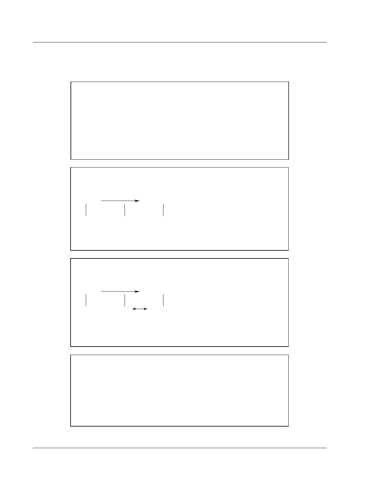
Message timeout = 1000 mSec (Rtimeout=1000)
Data Received on port:
TIME
0 1000 mSec 2000 mSec
A B C D E F G
Comment:
After the 'A' character is received on the port, the message timeout is started.
The characters "ABCDE" will be sent to the controller in one block. The characters
"FG" will follow in the second block one second later.
Intercharacter delay timeout used
Settings:
Intercharacter delay timeout = 300 mSec (Rdelay=300)
Data Received on port:
TIME
0 1000 mSec 2000 mSec
A B C D E F G H
>=300mSec time gap
Comment:
After each character is received, the intercharacter delay timer is reset. The characters
"ABCDEF" will be sent to the controller in one block because the delay timer expires.
The characters "GH" will follow in the second block when the next time gap is recognized.
Packet size limit used
Settings:
Packet size = 4 (RPacketLen=4)
Data Received on port:
A B C D E F G H I J
Comment:
The first block sent to the controller will contain the characters "ABCD", and the second
block will contain the characters "EFGH". The characters "IJ" will not be sent until two
more characters are received on the port.

Table of Contents

Question and Answer IconNeed help?

Do you have a question about the ProSoft Technology PLX3 Series and is the answer not in the manual?

ProSoft Technology PLX3 Series Specifications

General IconGeneral
BrandProSoft Technology
ModelPLX3 Series
CategoryGateway
LanguageEnglish

Summary

Start Here

System Requirements

Details the minimum hardware and software components required for the ProSoft Configuration Builder.

Package Contents

Lists the components included with the gateway, essential for installation and configuration.

Mounting the Gateway on a DIN-rail

Provides instructions and diagrams for physically mounting the gateway unit.

Jumper Settings

Explains the function and usage of the three sets of jumper settings on the module.

SD Card

Details the behavior and usage of the optional SD card for configuration data.

Connecting Power to the PLX3x Gateway

Provides instructions on how to properly connect power to the gateway unit.

Configuring Your Gateway

Installing ProSoft Configuration Builder Software

Guides users through the installation process of the ProSoft Configuration Builder software.

Using the Online Help

Explains how to access and utilize the integrated Help system for ProSoft Configuration Builder.

Setting Up the Project

Details the initial steps for setting up a new project within the ProSoft Configuration Builder.

Renaming PCB Objects

Describes how to rename project objects within the ProSoft Configuration Builder interface.

Configuring the Drivers

Provides steps for configuring the various drivers within the gateway's setup.

Using the CommonNet Data Map

Explains the advanced feature for copying data between gateway memory areas.

Configuring an IP Address

Details the procedure for configuring the gateway's Ethernet network settings, including IP address.

Downloading the Project to the Gateway

Guides users on how to transfer the configured project file from the PC to the gateway.

Printing a Configuration File

Explains how to print the current gateway configuration settings.

Diagnostics and Troubleshooting

LED Indicators

Describes the status and meaning of the gateway's LED indicators for troubleshooting.

Using Diagnostics in ProSoft Configuration Builder

Explains how to use the ProSoft Configuration Builder's diagnostic tools.

Gateway Status Data in Upper Memory

Details the location and meaning of gateway status data stored in upper memory.

Hardware Information

Hardware Specifications

Provides detailed specifications for the gateway's hardware components and capabilities.

Serial Port Cables (for Gateways with Serial Ports)

Offers information on cable types and pin assignments for the gateway's serial ports.

EIP Protocol

EIP Functional Overview

Provides a high-level overview of the EtherNet/IP protocol's functionality and capabilities.

EIP Configuration

Details the configuration steps for various EIP connection types, including Class 3 Server and Class 1.

EIP Diagnostics

Explains how to use ProSoft Configuration Builder for EIP driver diagnostics.

EIP Reference

Covers specific references for EIP, including SLC and MicroLogix, PLC5, and ControlLogix processors.

MBTCP Protocol

MBTCP Functional Overview

Introduces the Modbus TCP/IP protocol and its functionality for the gateway.

MBTCP Configuration

Details the configuration parameters for MBTCP servers and clients.

MBTCP Diagnostics

Explains how to perform diagnostics for the MBTCP driver using ProSoft Configuration Builder.

MBTCP Reference

Provides reference information on the Modbus protocol specification and function codes.

MBS Protocol

MBS Functional Overview

Describes the Modbus Serial protocol's Master and slave capabilities.

MBS Configuration

Details the configuration parameters for MBS ports, including Master and Slave settings.

MBS Diagnostics

Explains how to access diagnostic information for the MBS driver.

MBS Reference

Covers Modbus protocol specifications relevant to MBS, including function codes.

ASCII Protocol

ASCII Functional Overview

Introduces the ASCII protocol for interfacing with ASCII devices.

ASCII Configuration

Details the configuration parameters for ASCII ports, including data flow and modes.

ASCII Diagnostics

Explains how to perform diagnostics for the ASCII driver.

SIE Protocol

SIE Functional Overview

Provides an overview of the Siemens Industrial Ethernet (SIE) protocol.

SIE Configuration

Details the configuration steps for SIE clients and commands.

SIE Diagnostics

Explains how to access diagnostic information for the SIE driver and its error codes.

SIE Reference

Covers SIE references, including maximum register counts for various Siemens CPUs.

PND Protocol

PND Functional Overview

Introduces the PROFINET protocol and its benefits for automation.

PND Configuration

Guides users through configuring the PLX31-EIP-PND module using ProSoft Configuration Builder.

Step 7 Configuration

Details the tasks required to set up the module with Siemens Step 7 software.

PND Input/Output Error Status

Provides information on PND driver status, error codes, and connection status.

Support, Service and Warranty

Contacting Technical Support

Details how to contact ProSoft Technical Support and the information needed.

Warranty Information

Provides information on ProSoft Technology's terms and conditions for sale, warranty, and support.

Related product manuals