PLX3x Series EIP Protocol
Ethernet and Serial Gateways User Manual
ProSoft Technology, Inc. Page 91 of 218
May 26, 2016
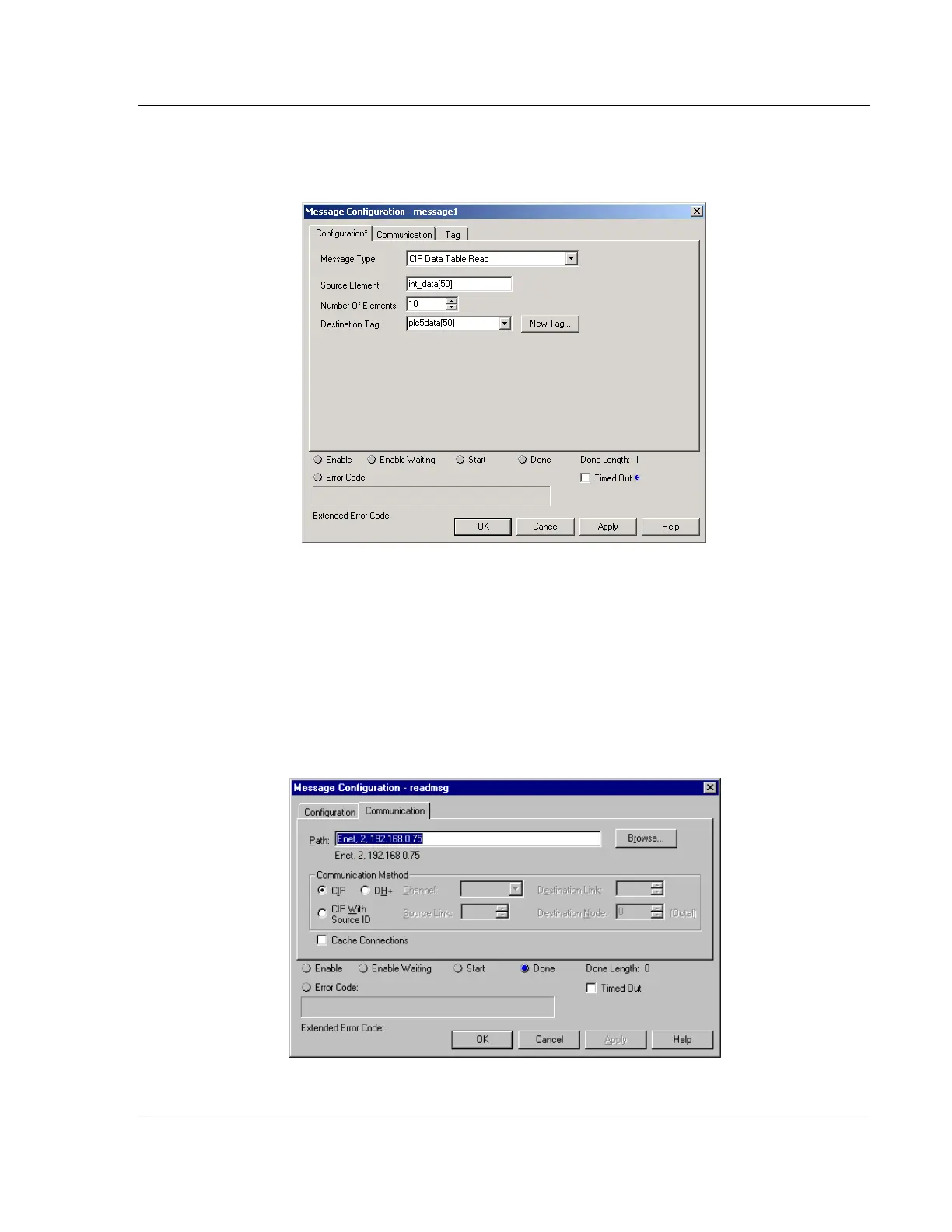
The MESSAGE CONFIGURATION dialog box must be completed to define the
data set to transfer to the processor from the gateway. An example of the dialog
box follows:
Complete the dialog box for the data area to be transferred. CIP Data Table
messages require a tag database element for both the source and destination.
The DESTINATION TAG is a tag defined in the Controller Tag database. The
SOURCE ELEMENT is the tag element in the EIP gateway. The gateway
simulates a tag database as an array of elements defined by the maximum
register size for the gateway (user configuration parameter "Maximum Register"
in the [Gateway] section) with the tag name INT_DATA. In the example above,
the first element in the database is the starting location for the read operation of
ten elements. Additionally, the COMMUNICATION information must also be
configured. An example of the dialog box follows: